HEATING / AIR CONDITIONING CONDENSER INSTALLATION
PROCEDURE

 88450
1.INSTALL CONDENSER ASSEMBLY WITH RECEIVER
Install the hybrid radiator assembly to the condenser assembly with receiver with the 4 bolts.
- Torque:
- 9.0 N*m (92 kgf*cm, 80 in.*lbf)
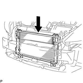
Install the condenser assembly with receiver as shown in the illustration.
- HINT:
-
If the condenser is replaced with a new one, add compressor oil to the new condenser.
- Compressor oil:
ND-11 or equivalent
- NOTICE:
-
Do not use any compressor oil other than ND-OIL 11 or equivalent. If any compressor oil other than ND-OIL 11 or equivalent is used, compressor motor insulation performance may decrease, resulting in a leakage of electric power.
16712
2.INSTALL NO. 2 FAN SHROUD
53208A
3.INSTALL HOOD LOCK SUPPORT SUB-ASSEMBLY
88710E
4.CONNECT AIR CONDITIONER TUBE AND ACCESSORY ASSEMBLY
Remove the vinyl tape from the pipe and the connecting part of the condenser assembly with receiver.
Sufficiently apply compressor oil to a new O-ring and the fitting surface of the pipe joint.
- NOTICE:
-
Keep the O-ring and O-ring fitting surfaces clean from dirt or any foreign objects.
Install the O-ring to the air conditioner tube and accessory assembly.
- Compressor oil:
ND-OIL 11 or equivalent
- NOTICE:
- ·
Keep the O-ring and O-ring fitting surfaces clean from dirt or any foreign objects.
·Do not use any compressor oil other than ND-OIL 11 or equivalent. If any compressor oil other than ND-OIL 11 or equivalent is used, compressor motor insulation performance may decrease, resulting in a leakage of electric power.
Install the air conditioner tube and accessory assembly on the condenser assembly with receiver with the bolt.
- Torque:
- 5.4 N*m (55 kgf*cm, 48 in.*lbf)
88711
5.CONNECT NO. 1 COOLER REFRIGERANT DISCHARGE HOSE
Remove the vinyl tape from the hose and the connecting part of the condenser assembly with receiver.
Sufficiently apply compressor oil to a new O-ring and the fitting surface of the hose joint.
- NOTICE:
-
Keep the O-ring and O-ring fitting surfaces clean from dirt or any foreign objects.
- Compressor oil:
ND-OIL 11 or equivalent
Install the O-ring to the No. 1 cooler refrigerant discharge hose.
- NOTICE:
- ·
Keep the O-ring and O-ring fitting surfaces clean from dirt or any foreign objects.
·Do not use any compressor oil other than ND-OIL 11 or equivalent. If any compressor oil other than ND-OIL 11 or equivalent is used, compressor motor insulation performance may decrease, resulting in a leakage of electric power.
Install the No. 1 cooler refrigerant discharge hose on the condenser assembly with receiver with the bolt.
- Torque:
- 5.4 N*m (55 kgf*cm, 48 in.*lbf)
G9225K
6.CONNECT NO. 1 INVERTER COOLING HOSE
Using pliers, grip the claws of the clip and slide the clip to connect the No. 1 inverter cooling hose.
- NOTICE:
-
To prevent entry of foreign matter, do not remove the vinyl tape from the No. 1 inverter cooling hose and condenser assembly with receiver until just before installing the No. 1 inverter cooling hose.
G9229A
7.CONNECT NO. 5 INVERTER COOLING HOSE
Using pliers, grip the claws of the clip and slide the clip to connect the No. 5 inverter cooling hose.
- NOTICE:
-
To prevent entry of foreign matter, do not remove the vinyl tape from the No. 5 inverter cooling hose and condenser assembly with receiver until just before installing the No. 5 inverter cooling hose.
G9214
8.INSTALL NO. 1 INVERTER BRACKET
88215
9.INSTALL NO. 1 MILLIMETER WAVE RADAR SENSOR BRACKET (w/ Dynamic Radar Cruise Control System)
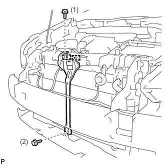
Engage the 2 guides.
Install the No. 1 millimeter wave radar sensor bracket with the 2 bolts.
- Torque:
- 6.2 N*m (63 kgf*cm, 55 in.*lbf)
- NOTICE:
-
Tighten the bolts in the order shown in the illustration to install the No. 1 millimeter wave radar sensor bracket.
88211B
10.INSTALL MILLIMETER WAVE RADAR SENSOR ASSEMBLY (w/ Dynamic Radar Cruise Control System)
11.INSTALL FRONT BUMPER ASSEMBLY
12.CONNECT CABLE TO NEGATIVE AUXILIARY BATTERY TERMINAL
- NOTICE:
-
When disconnecting the cable, some systems need to be initialized after the cable is reconnected (See page General>INTRODUCTION>REPAIR INSTRUCTION>INITIALIZATION).
64995
13.INSTALL DECK FLOOR BOX RH
64993
14.INSTALL REAR DECK FLOOR BOX
58412A
15.INSTALL NO. 2 DECK BOARD
58411A
16.INSTALL NO. 1 DECK BOARD
58410B
17.INSTALL DECK BOARD ASSEMBLY
18.ADD COOLANT (for Inverter)
19. CHARGE AIR CONDITIONING SYSTEM WITH REFRIGERANT (for HFC-134a(R134a))
20. CHARGE AIR CONDITIONING SYSTEM WITH REFRIGERANT (for HFO-1234yf(R1234yf))
21.WARM UP COMPRESSOR (for HFC-134a(R134a))
22.WARM UP COMPRESSOR (for HFO-1234yf(R1234yf))
23.INSPECT FOR REFRIGERANT LEAK (for HFC-134a(R134a))
24.INSPECT FOR REFRIGERANT LEAK (for HFO-1234yf(R1234yf))
25.INSPECT FOR COOLANT LEAK (for Inverter)
26.ADJUST HOOD SUB-ASSEMBLY
88211B
27.ADJUST MILLIMETER WAVE RADAR SENSOR ASSEMBLY (w/ Dynamic Radar Cruise Control System)