K111F MULTIDRIVE / CVT TRANSMISSION CONTROL CABLE INSTALLATION
PROCEDURE

 1.INSTALL TRANSMISSION CONTROL CABLE ASSEMBLY
- NOTICE:
-
Before installing the transmission control cable assembly, check that the park/neutral position switch assembly and shift lever are in neutral.
Put the transmission control cable assembly into the cabin and connect the transmission control cable assembly with the 2 bolts.
- Torque:
- 5.0 N*m (51 kgf*cm, 44 in.*lbf)
Connect the clamp of the transmission control cable assembly with the bolt.
- Torque:
- 5.0 N*m (51 kgf*cm, 44 in.*lbf)
Connect the transmission control cable assembly to the control cable support.
Connect the transmission control cable assembly to the bracket with a new clip.
Connect the transmission control cable assembly to the control shaft lever with the nut.
- Torque:
- 12 N*m (122 kgf*cm, 9 ft.*lbf)
Turn the nut of the transmission control cable 180° counterclockwise. While holding the nut in place, push in the stopper to lock the nut.
- NOTICE:
-
Do not over-rotate the nut as it will come off the internal spring and the transmission control cable will not be reusable.
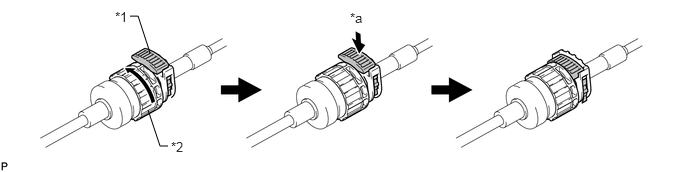
| *1 | Stopper | *2 | Nut |
| *a | Push in | - | - |
- HINT:
-
If the stopper cannot be pushed in, slightly turn the nut clockwise and then push in the stopper again.
Install the outer part of the transmission control cable assembly to the shift lever retainer. Check that the stopper returns to the pulled out position.
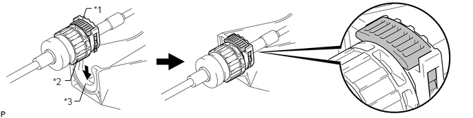
| *1 | Stopper | *2 | Nut |
| *3 | Shift Lever Retainer | - | - |
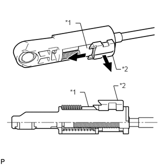
| *1 | Slider |
| *2 | Lock Piece |
Slide the slider in the direction shown in the illustration and pull out the lock piece.
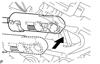
Connect the end of the transmission control cable assembly to the shift lever.
- NOTICE:
- ·
Make sure that the lock piece is pulled up.
·Push on the end of the transmission control cable assembly all the way to the base of the pin.
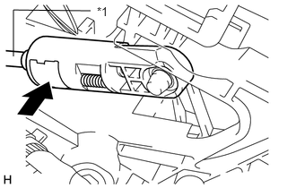
| *1 | Cable Rod |
Gently pull the cable rod toward the rear of the vehicle by hand to pull the cable taut.
Push the lock piece into the adjuster case and lock it.
- NOTICE:
-
Make sure that the lock piece is completely locked by the slider.
50819
2.INSTALL FRONT FLOOR COVER
17700
3.INSTALL AIR CLEANER CASE
17705
4.INSTALL AIR CLEANER CAP AND HOSE
74414B
5.INSTALL BATTERY BRACKET REINFORCEMENT
74411B
6.INSTALL FRONT BATTERY BRACKET
74431
7.INSTALL BATTERY TRAY
28800
8.INSTALL BATTERY
74404A
9.INSTALL BATTERY CLAMP SUB-ASSEMBLY
11212
10.INSTALL NO. 2 CYLINDER HEAD COVER
11.CONNECT CABLE TO NEGATIVE BATTERY TERMINAL
- NOTICE:
-
When disconnecting the cable, some systems need to be initialized after the cable is reconnected.
-
Click hereGeneral>INTRODUCTION>REPAIR INSTRUCTION>INITIALIZATION
12.INSPECT SHIFT LEVER POSITION
13.ADJUST SHIFT LEVER POSITION
58901A
14.INSTALL REAR CONSOLE BOX SUB-ASSEMBLY