3ZR-FE ENGINE MECHANICAL ENGINE UNIT REASSEMBLY
PROCEDURE

 1.INSTALL STIFFENING CRANKCASE RING PIN
- NOTICE:
-
It is not necessary to remove a ring pin unless it is being replaced.
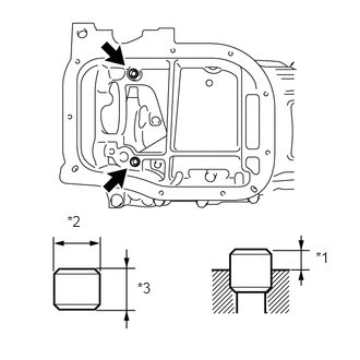
| *1 | Protrusion Height |
| *2 | Width |
| *3 | Height |
Using a plastic-faced hammer, tap in 2 new ring pins until they stop.
- Standard Ring Pin:
Protrusion Height Height Width 3.0 mm (0.118 in.) 11 mm (0.433 in.) 8.0 mm (0.315 in.)
- HINT:
-
The amount of protrusion may vary, but 3.0 mm (0.118 in.) is typical.
2.INSTALL STUD BOLT
- NOTICE:
-
If a stud bolt is deformed or the threads are damaged, replace it.
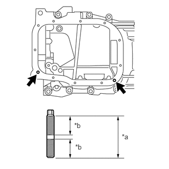
| *a | 23 mm (0.906 in.) |
| *b | 9.0 mm (0.354 in.) |
Using an E6 "TORX" socket wrench, install the stud bolts as shown in the illustration.
- Torque:
- 5.0 N*m (51 kgf*cm, 44 in.*lbf)
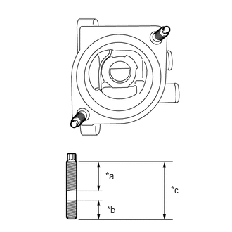
| *a | 21 mm (0.827 in.) |
| *b | 9.0 mm (0.354 in.) |
| *c | 34 mm (1.34 in.) |
Using an E6 "TORX" socket wrench, install the stud bolts as shown in the illustration.
- Torque:
- 5.0 N*m (51 kgf*cm, 44 in.*lbf)
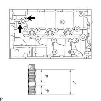
| *a | 12 mm (0.472 in.) |
| *b | 9.0 mm (0.354 in.) |
| *c | 23 mm (0.906 in.) |
Using an E5 "TORX" socket wrench, install the stud bolts as shown in the illustration.
- Torque:
- 5.0 N*m (51 kgf*cm, 44 in.*lbf)
11420
3.INSTALL STIFFENING CRANKCASE ASSEMBLY
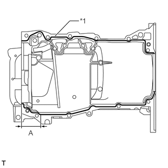
| *1 | Seal Packing |
Apply seal packing in a continuous line as shown in the illustration.
- Seal packing:
Toyota Genuine Seal Packing Black, Three bond 1207B or equivalent
- Standard Seal Diameter:
Area Specified Condition except Area A 2.0 to 3.0 mm (0.0787 to 0.118 in.) for Area A 4.5 to 5.5 mm (0.177 to 0.217 in.)
- Application Length A:
56 mm (2.20 in.)
- NOTICE:
- ·
Remove any oil from the contact surfaces.
·Install the crankcase within 3 minutes and tighten the bolts within 15 minutes after applying seal packing.
·Do not start the engine for at least 2 hours after installing the stiffening crankcase assembly.
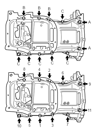
Install the stiffening crankcase with the 11 bolts in the sequence shown in the illustration.
- Torque:
- 21 N*m (214 kgf*cm, 15 ft.*lbf)
- Bolt Length:
Item Specified Condition Bolt A 138 mm (5.43 in.) Bolt B 35 mm (1.38 in.) Bolt C 70 mm (2.76 in.)
Recheck the torque for bolts 1 and 2.
- Torque:
- 21 N*m (214 kgf*cm, 15 ft.*lbf)
Wipe off any excess seal packing with a clean piece of cloth.
15100
4.INSTALL OIL PUMP ASSEMBLY
12102A
5.INSTALL NO. 2 OIL PAN SUB-ASSEMBLY
12101A
6.INSTALL OIL PAN DRAIN PLUG
Install a new gasket and the oil pan drain plug.
- Torque:
- 37 N*m (377 kgf*cm, 27 ft.*lbf)
11401L
7.INSTALL ENGINE REAR OIL SEAL
11432A
8.INSTALL NO. 1 TAPER SCREW PLUG
Clean the No. 1 taper screw plug and plug hole.
Apply adhesive to 2 or 3 threads of the No. 1 taper screw plug. Then install the No. 1 taper screw plug.
- Adhesive:
Toyota Genuine Adhesive 1344, Three Bond 1344 or equivalent
- Torque:
- 25 N*m (255 kgf*cm, 18 ft.*lbf)
- NOTICE:
- ·
Install the plug within 3 minutes of applying adhesive.
·Do not start the engine within 1 hour of installing the plug.
12204
9.INSTALL PCV VALVE SUB-ASSEMBLY
11115
10.INSTALL CYLINDER HEAD GASKET
11101
11.INSTALL CYLINDER HEAD SUB-ASSEMBLY
13716
12.INSTALL VALVE STEM CAP
Apply a light coat of engine oil to the valve stem ends.
Install the 16 valve stem caps to the cylinder head.
- NOTICE:
-
Do not drop the valve stem caps into the cylinder head.
13750
13.INSTALL VALVE LASH ADJUSTER ASSEMBLY
Inspect each valve lash adjuster before installing it.
Click hereEngine / Hybrid System>3ZR-FE ENGINE MECHANICAL>ENGINE UNIT>INSPECTION
Install the 16 valve lash adjuster assemblies to the cylinder head.
- NOTICE:
-
Install the valve lash adjuster to the same place it was removed from.
13801
14.INSTALL NO. 1 VALVE ROCKER ARM SUB-ASSEMBLY
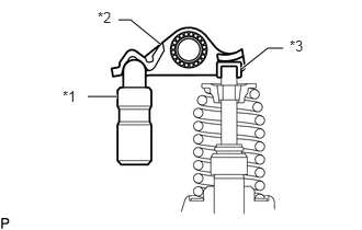
| *1 | Lash Adjuster |
| *2 | Valve Rocker Arm |
| *3 | Valve Stem |
| *4 | Valve Stem Cap |
Apply engine oil to the valve lash adjuster tips and valve stem cap ends.
Make sure that the No. 1 valve rocker arm assemblies are installed as shown in the illustration.
11114A
15.INSTALL CAMSHAFT HOUSING STRAIGHT PIN
- NOTICE:
-
It is not necessary to remove a straight pin unless it is being replaced.
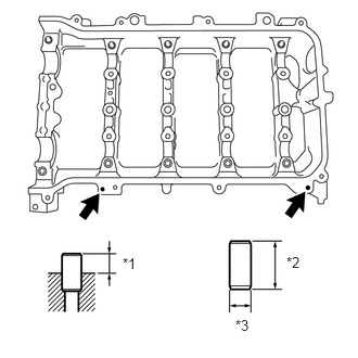
| *1 | Protrusion Height |
| *2 | Height |
| *3 | Width |
Using a plastic-faced hammer, tap in a new straight pin to the specified protrusion height.
- Standard Straight Pin:
Protrusion Height Height Width 6.5 to 7.5 mm (0.256 to 0.295 in.) 14 mm (0.551 in.) 6.0 mm (0.236 in.)
11811
16.INSTALL NO. 1 CAMSHAFT BEARING
15678A
17.INSTALL OIL CONTROL VALVE FILTER
Check that no foreign matter is on the mesh part of the oil control valve filter.
Install the oil control valve filter.
- NOTICE:
-
Do not touch the mesh when installing the oil control valve filter.
11821
18.INSTALL NO. 2 CAMSHAFT BEARING
13512
19.INSTALL NO. 2 CAMSHAFT
13511
20.INSTALL CAMSHAFT
21.INSTALL CAMSHAFT BEARING CAP
11103
22.INSTALL CAMSHAFT HOUSING SUB-ASSEMBLY
13050
23.INSTALL CAMSHAFT TIMING GEAR ASSEMBLY
13070A
24.INSTALL CAMSHAFT TIMING EXHAUST GEAR ASSEMBLY
13521A
25.INSTALL CRANKSHAFT TIMING GEAR KEY
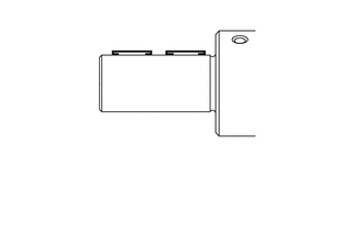
Using a plastic-faced hammer, tap in the 2 crankshaft timing gear keys.
- HINT:
-
Tap in the crankshaft timing gear keys until they contact the crankshaft as shown in the illustration.
19315
26.INSTALL NO. 1 CRANKSHAFT POSITION SENSOR PLATE
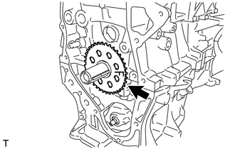
Install the sensor plate with the "F" mark facing forward.
13507
27.INSTALL NO. 2 CHAIN SUB-ASSEMBLY
13521
28.INSTALL CRANKSHAFT TIMING SPROCKET
13561
29.INSTALL NO. 1 CHAIN VIBRATION DAMPER
Install the No. 1 chain vibration damper with the 2 bolts.
- Torque:
- 21 N*m (214 kgf*cm, 15 ft.*lbf)
13562
30.INSTALL NO. 2 CHAIN VIBRATION DAMPER
31.SET NO. 1 CYLINDER TO TDC/COMPRESSION
Temporarily install the crankshaft pulley bolt.
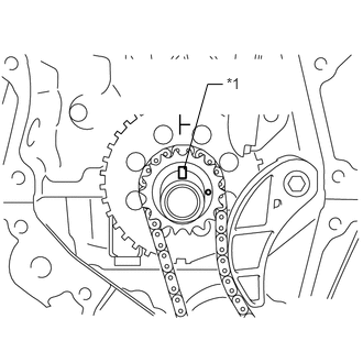
| *1 | Timing Gear Key |
Turn the crankshaft counterclockwise to position the timing gear key at the top.
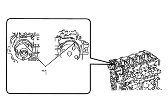
| *1 | Timing Mark |
Check that the timing marks on the camshaft timing gear and camshaft timing exhaust gear assembly are aligned as shown in the illustration.
Remove the crankshaft pulley bolt.
13506
32.INSTALL CHAIN SUB-ASSEMBLY
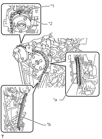
| *1 | Mark Plate (Orange) |
| *2 | Timing Mark |
| *a | Place the Chain on the Sprocket |
| *b | Pass the Chain through the Damper |
Align the mark plate (orange) with the timing mark as shown in the illustration and install the chain sub-assembly.
- HINT:
- ·
Be sure to position the mark plate at the front of the engine.
·The mark plate on the camshaft side is colored orange.
·Do not engage the chain with the sprocket of the camshaft timing gear. Only place it on the camshaft timing gear.
·Pass the chain through the No. 1 vibration damper.
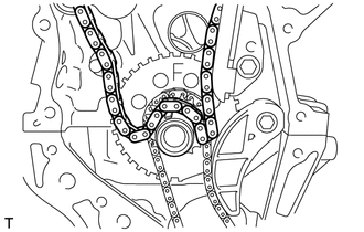
Place the chain on the crankshaft without passing it around the shaft.
Hold the hexagonal portion of the camshaft with a wrench and turn the camshaft timing gear counterclockwise to align the mark plates (orange) and timing mark, and then install the chain sub-assembly.
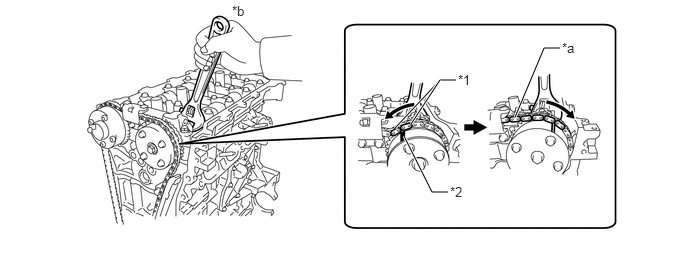
| *1 | Mark Plate (Orange) | *2 | Timing Mark |
| *a | Apply Tension to the Chain | *b | Turn |
- HINT:
-
To apply tension to the chain, slowly turn the camshaft timing gear assembly and camshaft timing exhaust gear assembly clockwise to prevent the chain sub-assembly from being misaligned.
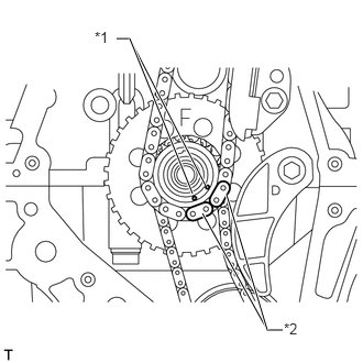
| *1 | Timing Mark |
| *2 | Mark Plate (Pink) |
Align the mark plate (pink) and timing marks and install the chain sub-assembly to the crankshaft timing sprocket.
13559
33.INSTALL CHAIN TENSIONER SLIPPER
34.CHECK NO. 1 CYLINDER TO TDC/COMPRESSION
Check each timing mark with the No. 1 cylinder at TDC/compression.
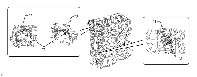
| *1 | Timing Mark | *2 | Mark Plate (Orange) |
| *3 | Mark Plate (Pink) | - | - |
12511
35.INSTALL NO. 1 GENERATOR BRACKET
Install the No. 1 generator bracket with the 4 bolts.
- Torque:
- 24 N*m (245 kgf*cm, 18 ft.*lbf)
16323
36.INSTALL WATER INLET HOUSING
Install a new gasket and the water inlet housing with the 3 bolts.
- Torque:
- 21 N*m (214 kgf*cm, 15 ft.*lbf)
11302
37.INSTALL TIMING CHAIN COVER SUB-ASSEMBLY
11302A
38.INSTALL TIMING CHAIN COVER OIL SEAL
39.INSTALL ENGINE MOUNTING BRACKET STUD BOLT
- NOTICE:
-
If a stud bolt is deformed or the threads are damaged, replace it.
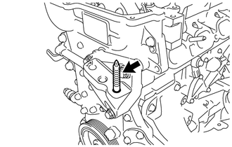
Install the stud bolt.
- Torque:
- 10 N*m (102 kgf*cm, 7 ft.*lbf)
13471
40.INSTALL CRANKSHAFT PULLEY
13540
41.INSTALL NO. 1 CHAIN TENSIONER ASSEMBLY
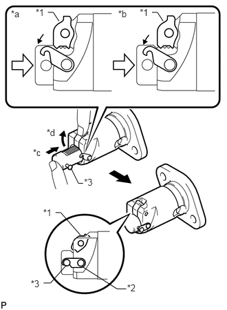
| *1 | Cam |
| *2 | Hook |
| *3 | Pin |
| *a | CORRECT |
| *b | INCORRECT |
| *c | Push |
| *d | Raise |
Release the ratchet pawl. Then fully push in the plunger and attach the hook to the pin so that the plunger is in the position shown in the illustration.
- NOTICE:
-
Make sure that the cam engages with the first tooth of the plunger to allow the hook to pass over the pin.
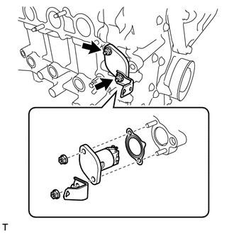
Install a new gasket, the bracket and the No. 1 chain tensioner with the 2 nuts.
- Torque:
- 12 N*m (122 kgf*cm, 9 ft.*lbf)
- NOTICE:
-
If the hook becomes detached from the plunger while the chain tensioner is being installed, attach the hook again.
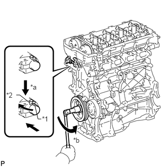
| *1 | Pin |
| *2 | Hook |
| *a | Release |
| *b | Turn |
Turn the crankshaft counterclockwise slightly and check that the hook is released.
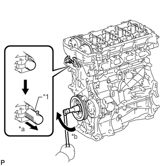
| *1 | Plunger |
| *a | Plunger Extended |
| *b | Turn |
Turn the crankshaft clockwise and check that the plunger is extended.
15600A
42.INSTALL OIL FILTER UNION (for Oil Filter Sub-assembly Type)
Using a 12 mm socket hexagon wrench, install the oil filter union.
- Torque:
- 29.5 N*m (301 kgf*cm, 22 ft.*lbf)
43.INSTALL OIL FILTER
11193
44.INSTALL SPARK PLUG TUBE GASKET
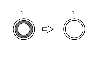
| *a | Before Cutting |
| *b | After Cutting |

|
Area to be Cut Off |
Using a cutter knife, cut off the seal part of the removed spark plug tube gasket.
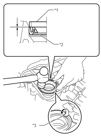
| *1 | Spark Plug Tube Gasket without Sealing Part |
| *2 | New Plug Plug Tube Gasket |
| *3 | Claw |
Using a hammer and the removed spark plug tube gasket which has had the sealing part cut off, uniformly tap in a new spark plug tube gasket all the way.
- NOTICE:
- ·
Keep the lip free of foreign matter.
·Do not tap in the spark plug tube gasket at an angle.
- HINT:
-
If a spark plug tube gasket that will be used to install a new spark plug tube gasket is deformed and cannot be positioned on a new spark plug tube gasket, correct the deformation using pliers.
Return the claws of the ventilation baffle plate to their original positions.
11213
45.INSTALL CYLINDER HEAD COVER GASKET
Install a new cylinder head cover gasket to the cylinder head cover.
- NOTICE:
-
Remove any oil from the contact surfaces.
11201
46.INSTALL CYLINDER HEAD COVER SUB-ASSEMBLY
Install 3 new gaskets to the camshaft bearing cap.
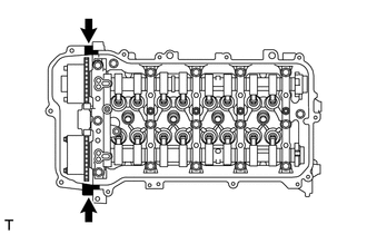
Apply seal packing as shown in the illustration.
- Seal packing:
Toyota Genuine Seal Packing Black, Three Bond 1207B or equivalent
- Standard diameter:
4.0 mm (0.157 in.)
- NOTICE:
- ·
Remove any oil from the contact surfaces.
·Install the cylinder head cover sub-assembly within 3 minutes and tighten the bolts within 15 minutes after applying seal packing.
Install the cylinder head cover with a new seal washer and the 13 bolts.
- Torque:
- 10 N*m (102 kgf*cm, 7 ft.*lbf)
- NOTICE:
-
Do not start the engine for at least 2 hours after the installation.
83530
47.INSTALL ENGINE OIL PRESSURE SWITCH ASSEMBLY
89422
48.INSTALL ENGINE COOLANT TEMPERATURE SENSOR
89615
49.INSTALL KNOCK SENSOR
11401G
50.INSTALL CRANKSHAFT POSITION SENSOR
11101J
51.INSTALL CAMSHAFT TIMING OIL CONTROL VALVE ASSEMBLY (for Intake Side)
52.INSTALL CAMSHAFT TIMING OIL CONTROL VALVE ASSEMBLY (for Exhaust Side)
11101W
53.INSTALL CAMSHAFT POSITION SENSOR (for Intake Side)
54.INSTALL CAMSHAFT POSITION SENSOR (for Exhaust Side)
19100P
55.INSTALL SPARK PLUG
12635
56.INSTALL ENGINE COVER JOINT
Install the 2 engine cover joints.
- Torque:
- 10 N*m (102 kgf*cm, 7 ft.*lbf)
12108A
57.INSTALL OIL FILLER CAP GASKET
Install the gasket to the oil filler cap.
12108
58.INSTALL OIL FILLER CAP SUB-ASSEMBLY
Install the oil filler cap sub-assembly.