2WW FUEL FUEL INJECTOR INSTALLATION
CAUTION / NOTICE / HINT
- NOTICE:
- ·
Always be sure to check the tightening torque.
·If the pressure lines are leaking after installation, they must be replaced.
·Do not overtighten the pressure lines.
PROCEDURE

 23670
1.INSTALL INJECTOR ASSEMBLY
- NOTICE:
- ·
Before installing the injector assembly, check for carbon, foreign matter, etc. on the sealing surfaces of the cylinder head sub-assembly and injector assembly. If there is foreign matter, remove it before installing the injector assembly.
·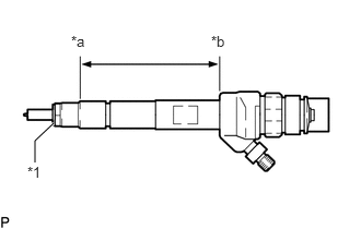 0.333,1.552 0.333,1.344 0.333,1.344 0.51,1.177 true 0.26,1.563 0.573,1.719 0.313,0.156 10 false *1 0.677,0.313 0.938,0.583 0.26,0.271 10 false *a 2.01,0.313 2.25,0.521 0.24,0.208 10 false *b
*1 Copper Sealing Ring *a Point Above the Copper Sealing Ring *b Injector Assembly Slot End
Make sure to replace the copper sealing ring on the injector assembly.
·Before installing the injector assemblies to the injector assembly slots, apply a light coat of highly heat-resistant grease from above the top of the copper sealing ring to the injector assembly slot end.
·Check the installation position of the high pressure connection.
·Make sure to read the adjustment values each time new injector assemblies are installed.
Install the 4 injector assemblies to the cylinder head cover sub-assembly.
Using an E10 "TORX" socket wrench, install the 4 clamping claws to the 4 injector assemblies with the 4 centering rings and 4 bolts.
- Torque:
- 10 N*m (102 kgf*cm, 7 ft.*lbf)
- NOTICE:
- ·
Retighten the clamping claw (cylinder head cover mounting).
·Make sure the screw centering ring is correctly positioned in order to align the clamping claw.
Connect the 4 injector assembly connectors.
23760
2.CONNECT NOZZLE LEAKAGE PIPE ASSEMBLY
Install 4 new sealing rings to the nozzle leakage pipe assembly.
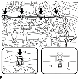
| *1 | Sealing Ring |
| *a | Leakage Line |
| *b | Clip |
| *c | Push down |
Connect the nozzle leakage pipe assembly to the 4 injector assemblies and push down the 4 clips to install the nozzle leakage pipe assembly.
Connect the connector and attach the 2 clamps to connect the wire harness.
3.INSTALL CAMSHAFT POSITION SENSOR
4.INSTALL INJECTION PIPE SUB-ASSEMBLY
- NOTICE:
- ·
If the pressure lines are leaking after installation, they must be replaced.
·Do not overtighten the pressure lines.
Temporarily install the 2 No. 1 injection pipe sub-assemblies and 2 No. 2 injection pipe sub-assemblies at the common rail assembly end by hand.
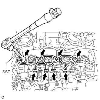
Using SST, tighten the 4 union nuts at the common rail assembly end of the 2 No. 1 injection pipe sub-assemblies and 2 No. 2 injection pipe sub-assemblies shown in the illustration.
- SST:
PZ4TB-04959-10
- Torque:
- 24 N*m (245 kgf*cm, 18 ft.*lbf)
- NOTICE:
-
Reset SST in a timely manner to prevent bending of pressure lines.
Using SST, tighten the 4 union nuts at the 4 injector assembly ends of the 2 No. 1 injection pipe sub-assemblies and 2 No. 2 injection pipe sub-assemblies.
- SST:
PZ4TB-04959-10
- Torque:
- 24 N*m (245 kgf*cm, 18 ft.*lbf)
- NOTICE:
-
Reset SST in a timely manner to prevent bending of pressure lines.
Check all components of the common rail system for tightness.
5.CONNECT CABLE TO NEGATIVE BATTERY TERMINAL
- NOTICE:
-
When disconnecting the cable, some systems need to be initialized after the cable is reconnected.
-
Click hereGeneral>INTRODUCTION>REPAIR INSTRUCTION>INITIALIZATION
6.INSPECT FOR FUEL LEAK
7.INSTALL ENGINE COVER
Install the engine cover.
12611
8.INSTALL NO. 1 ENGINE COVER
9.PERFORM REGISTRATION