BRAKE SYSTEM (OTHER) VACUUM PUMP(for M20A-FKS) REMOVAL
CAUTION / NOTICE / HINT
The necessary procedures (adjustment, calibration, initialization or registration) that must be performed after parts are removed and installed, or replaced during vacuum pump assembly removal/installation are shown below.
| Replaced Part or Performed Procedures | Necessary Procedures | Effect/Inoperative Function When Necessary Procedures are not Performed | Link |
|---|---|---|---|
|
*: When performing learning using the GTS. Click here( |
|||
| Battery terminal is disconnected/reconnected | Drive the vehicle until stop and start control is permitted (approximately 5 to 60 minutes) | Stop and start system | ( ) |
| Perform steering sensor zero point calibration | Lane control system | ()
|
|
| Parking support brake system (for Gasoline model)* | |||
| Pre-collision system | |||
| Memorize steering angle neutral point | Parking assist monitor system | ()
|
|
| Panoramic view monitor system (for Gasoline model) | ()
|
||
| Reset back door close position | Power back door system (for Gasoline model) | ()
|
|
| Power back door initialization | Power door lock control system | ()
|
|
- NOTICE:
- ·
After the ignition switch is turned off, the navigation system requires approximately a minute to record various types of memory and settings. As a result, after turning the ignition switch off, wait a minute or more before disconnecting the cable from the negative (-) battery terminal.
·This procedure includes the removal of small-head bolts. Refer to Small-Head Bolts of Basic Repair Hint to identify the small-head bolts.
Click hereGeneral>INTRODUCTION>REPAIR INSTRUCTION>PRECAUTION
PROCEDURE

 89661
1.REMOVE ECM
2.REMOVE BATTERY
74404A
3.REMOVE BATTERY CLAMP SUB-ASSEMBLY
44777
4.DISCONNECT NO. 1 VACUUM HOSE CONNECTOR
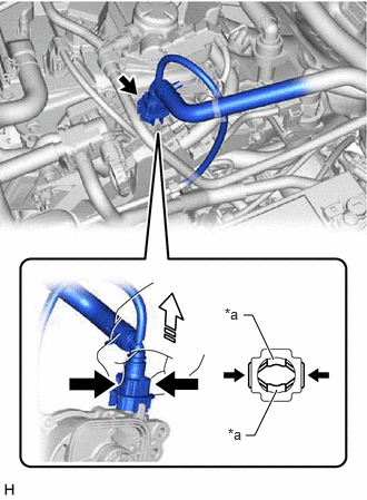
| *a | Retainer |

|
Pinch |

|
Pull off |
Pinch the retainer of the No. 1 vacuum hose connector, and then pull the No. 1 vacuum hose connector off of the vacuum pump assembly.
- NOTICE:
-
Be sure to disconnect the No. 1 vacuum hose connector by hand.
82121
5.SEPARATE ENGINE WIRE
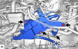
Disconnect the connector and disengage the clamp.
Remove the bolt, 2 nuts and separate the engine wire.
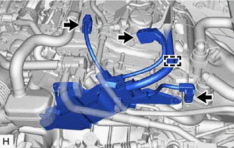
Disconnect the 3 connectors and disengage the clamp.
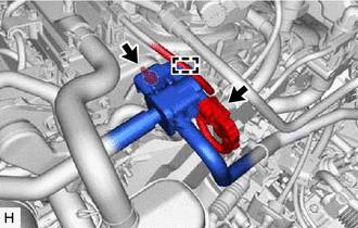
Disconnect the purge valve (purge VSV) connector.
Disengage the clamp.
Remove the bolt and separate the purge valve (purge VSV) from the purge VSV bracket.
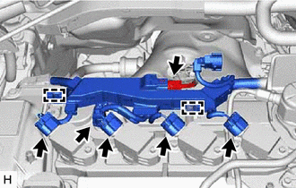
Disconnect the 6 connectors and disengage the 2 clamps.
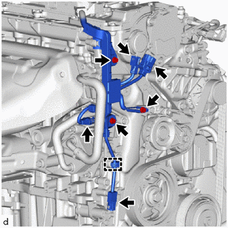
Disconnect the 4 connectors.
Disengage the clamp to separate the engine wire.
Remove the 3 bolts and separate the engine wire.
29300
6.REMOVE VACUUM PUMP ASSEMBLY
Move aside the engine wire.
- NOTICE:
-
Do not apply excessive force to the engine wire.
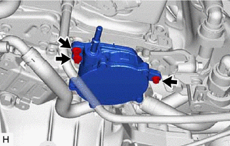
Using an 8 mm socket wrench, remove the 3 bolts and vacuum pump assembly from the engine assembly.
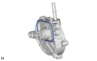
Remove the No. 1 vacuum pump O-ring from the vacuum pump assembly.