NETWORKING NETWORK GATEWAY ECU(for LHD) INSTALLATION
PROCEDURE

 89111
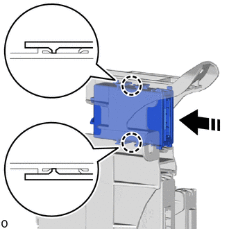
1.INSTALL NETWORK GATEWAY ECU

|
Install in this Direction |
Attach the claw to install the network gateway ECU.
82877
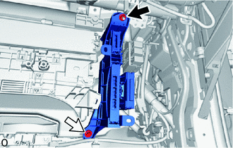
2.INSTALL ECU INTEGRATION BOX RH (except Manual Transaxle)

|
Nut |

|
Bolt |
Install the ECU integration box RH with the nut and bolt.
- Torque:
- Nut : 5.5 N*m (56 kgf*cm, 49 in.*lbf)
- Bolt : 5.5 N*m (56 kgf*cm, 49 in.*lbf)
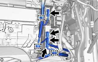
Attach the 3 wire harness clamps.
Connect the 4 connectors.
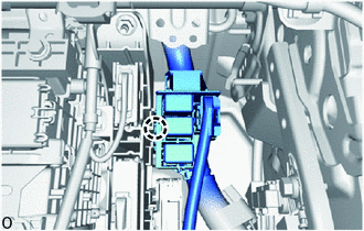
Attach the claw and relay holder.
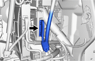
w/ Clearance Warning System:
Connect the connector.
82877
3.INSTALL ECU INTEGRATION BOX RH (for Manual Transaxle)
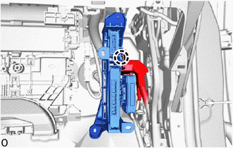
Attach the claw to install the wire harness protector and temporarily install the ECU integration box RH.
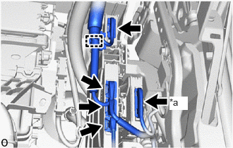
| *a | w/ Clearance Warning System |
w/ Clearance Warning System:
Connect the 5 connectors.
w/o Clearance Warning System:
Connect the 4 connectors.
Attach the wire harness clamp.
4.INSTALL INSTRUMENT PANEL JUNCTION BLOCK ASSEMBLY WITH MAIN BODY ECU (for Manual Transaxle)
55433B
5.INSTALL LOWER NO. 2 INSTRUMENT PANEL FINISH PANEL
55550
6.INSTALL GLOVE COMPARTMENT DOOR ASSEMBLY
55607
7.INSTALL NO. 2 INSTRUMENT PANEL UNDER COVER SUB-ASSEMBLY
62111C
8.INSTALL COWL SIDE TRIM BOARD RH
67913B
9.INSTALL FRONT DOOR SCUFF PLATE RH
- HINT:
-
Use the same procedure described for the LH side.
-
Click hereVehicle Interior>INTERIOR PANELS / TRIM>ROOF HEADLINING>INSTALLATION
58810J
10.INSTALL CONSOLE BOX ASSEMBLY
11.CONNECT CABLE TO NEGATIVE AUXILIARY BATTERY TERMINAL
for A25A-FKS:
for M20A-FKS:
for A25A-FXS:
Click hereGeneral>MAINTENANCE>A25A-FXS AUXILIARY BATTERY>INSTALLATION
for A25B-FXS:
Click hereGeneral>MAINTENANCE>A25B-FXS AUXILIARY BATTERY>INSTALLATION
- NOTICE:
-
When disconnecting the cable, some systems need to be initialized after the cable is reconnected.
-
Click hereGeneral>INTRODUCTION>REPAIR INSTRUCTION>INITIALIZATION
65351A
12.INSTALL BATTERY HOLE COVER (for HV Model)
for A25A-FXS:
Click hereGeneral>MAINTENANCE>A25A-FXS AUXILIARY BATTERY>INSTALLATION
for A25B-FXS:
Click hereGeneral>MAINTENANCE>A25B-FXS AUXILIARY BATTERY>INSTALLATION
58416K
13.INSTALL REAR NO. 2 FLOOR BOARD (for HV Model)
for A25A-FXS:
Click hereGeneral>MAINTENANCE>A25A-FXS AUXILIARY BATTERY>INSTALLATION
for A25B-FXS:
Click hereGeneral>MAINTENANCE>A25B-FXS AUXILIARY BATTERY>INSTALLATION
58410B
14.INSTALL DECK BOARD ASSEMBLY (for HV Model)
for A25A-FXS:
Click hereGeneral>MAINTENANCE>A25A-FXS AUXILIARY BATTERY>INSTALLATION
for A25B-FXS:
Click hereGeneral>MAINTENANCE>A25B-FXS AUXILIARY BATTERY>INSTALLATION
15. PERFORM DIAGNOSTIC SYSTEM CHECK (for Manual Transaxle)
for Gasoline Model with Occupant Classification System:
w/o Occupant Classification System:
16.CHECK SRS WARNING LIGHT (for Manual Transaxle)
for Gasoline Model with Occupant Classification System:
w/o Occupant Classification System: