AXLE AND DIFFERENTIAL FRONT AXLE HUB BOLT REPLACEMENT
CAUTION / NOTICE / HINT
The necessary procedures (adjustment, calibration, initialization, or registration) that must be performed after parts are removed and installed, or replaced during front axle hub bolt removal/installation are shown below.
| Replaced Part or Performed Procedure | Necessary Procedure | Effect/Inoperative Function when Necessary Procedure not Performed | Link |
|---|---|---|---|
|
*: When performing learning using the GTS. Click here( |
|||
| Auxiliary battery terminal is disconnected/reconnected | Perform steering sensor zero point calibration | Lane control system | ( ) |
| Parking support brake system (for HV model)* | |||
| Pre-collision system | |||
| Memorize steering angle neutral point | Parking assist monitor system | ()
|
|
| Panoramic view monitor system (for HV model) | ()
|
||
| Reset back door close position | Power back door system (for HV model) | ()
|
|
| Power back door initialization | Power door lock control system | ()
|
|
- NOTICE:
-
After the ignition switch is turned off, the navigation system requires approximately a minute to record various types of memory and settings. As a result, after turning the ignition switch off, wait a minute or more before disconnecting the cable from the negative (-) auxiliary battery terminal.
- HINT:
- ·
Use the same procedure for the RH and LH sides.
·The following procedure is for the LH side.
PROCEDURE

 1.DISABLE BRAKE CONTROL (w/o Vacuum Brake Booster)
Click hereBrake>BRAKE (REAR)>REAR BRAKE>REMOVAL
2.REMOVE FRONT WHEEL
47313J
3.DISCONNECT FRONT FLEXIBLE HOSE
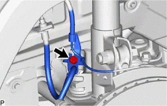
Remove the bolt and disconnect the front flexible hose from the front shock absorber assembly.
4.DISCONNECT FRONT DISC BRAKE CALIPER ASSEMBLY LH
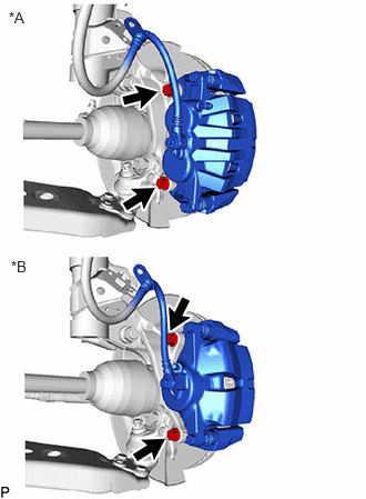
| *A | for 2-Pot Caliper |
| *B | except 2-Pot Caliper |
Remove the 2 bolts and disconnect the front disc brake caliper assembly LH from the steering knuckle.
- NOTICE:
-
Use wire or an equivalent tool to keep the front disc brake caliper assembly LH from hanging by the front flexible hose.
43512
5.REMOVE FRONT DISC
for 2-Pot Caliper: Click hereBrake>BRAKE (FRONT)>FRONT BRAKE (for 2-Pot Caliper)>REMOVAL
except 2-Pot Caliper: Click hereBrake>BRAKE (FRONT)>FRONT BRAKE (except 2-Pot Caliper)>REMOVAL
43502D
6.REMOVE FRONT AXLE HUB BOLT LH
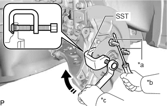
| *a | Service Nut |
| *b | Hold |
| *c | Turn |
Temporarily install 2 service nuts to the front axle hub bolts as shown in the illustration.
- Recommended service nut:
Thread diameter: 12.0 mm (0.472 in.)
Thread pitch: 1.5 mm (0.0591 in.)
- NOTICE:
-
Install the service nuts to prevent damage to the front axle hub bolts.
Using SST and a screwdriver or an equivalent tool to hold the front axle hub sub-assembly, remove the front axle hub bolt.
- SST
- 09650-17011
- NOTICE:
-
Do not damage the threads of the front axle hub bolts.
43502D
7.INSTALL FRONT AXLE HUB BOLT LH
Temporarily install a new front axle hub bolt to the front axle hub sub-assembly.
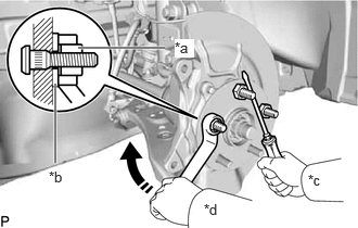
| *a | Service Nut |
| *b | Washer |
| *c | Hold |
| *d | Turn |
Install a washer and service nut to the front axle hub bolt as shown in the illustration.
- Recommended service nut:
Thread diameter: 12.0 mm (0.472 in.)
Thread pitch: 1.5 mm (0.0591 in.)
- HINT:
-
Recommended washer thickness is 5 mm (0.197 in.) or more.
Using a screwdriver or an equivalent tool to hold the front axle hub sub-assembly, install the front axle hub bolt by tightening the service nut.
- NOTICE:
- ·
Install the service nuts to prevent damage to the front axle hub bolts.
·Do not damage the threads of the front axle hub bolts.
Remove the 3 service nuts and washer from the 3 front axle hub bolts.
43512
8.INSTALL FRONT DISC
for 2-Pot Caliper: Click hereBrake>BRAKE (FRONT)>FRONT BRAKE (for 2-Pot Caliper)>INSTALLATION
except 2-Pot Caliper: Click hereBrake>BRAKE (FRONT)>FRONT BRAKE (except 2-Pot Caliper)>INSTALLATION
9.INSTALL FRONT DISC BRAKE CALIPER ASSEMBLY LH
Install the front disc brake caliper assembly LH to the steering knuckle with the 2 bolts.
- Torque:
- for Steel Steering Knuckle : 107 N*m (1091 kgf*cm, 79 ft.*lbf)
- for Aluminum Steering Knuckle : 150 N*m (1530 kgf*cm, 111 ft.*lbf)
- NOTICE:
- ·
Do not twist the front flexible hose when installing the front disc brake caliper assembly.
·Make sure that there is no foreign matter on the threads of the bolt.
47313J
10.CONNECT FRONT FLEXIBLE HOSE
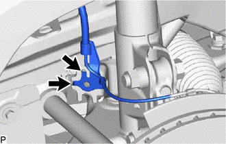

|
Hook |
Set the 2 front speed sensor LH hooks on the front shock absorber assembly LH.
- NOTICE:
-
Do not twist the front speed sensor when installing it.
Connect the front speed sensor and front flexible hose to the front shock absorber assembly with the bolt.
- Torque:
- 29 N*m (296 kgf*cm, 21 ft.*lbf)
- NOTICE:
-
Do not twist the front flexible hose when installing it.
11.INSTALL FRONT WHEEL
12.CONNECT CABLE TO NEGATIVE AUXILIARY BATTERY TERMINAL (w/o Vacuum Brake Booster)
Connect the reservoir level switch connector.
Connect the cable to the negative (-) auxiliary battery terminal.
for A25A-FXS: Click hereGeneral>MAINTENANCE>A25A-FXS AUXILIARY BATTERY>INSTALLATION
for A25B-FXS: Click hereGeneral>MAINTENANCE>A25B-FXS AUXILIARY BATTERY>INSTALLATION
Perform the following procedure if air bleeding is not necessary:
Turn the power switch on (READY).
Depress the brake pedal and release it.