DOOR / HATCH HOOD LOCK CONTROL CABLE ASSEMBLY(for RHD) INSTALLATION
PROCEDURE

 53630
1.INSTALL HOOD LOCK CONTROL CABLE ASSEMBLY
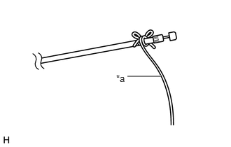
| *a | String |
Tie a string to the end of the hood lock control cable assembly in the engine room.
Pull the string from the cabin until the hood lock control cable assembly grommet contacts the vehicle.
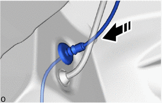

|
Install in this Direction |
Install the grommet as shown in the illustration.
Attach the clamp and install the hood lock control cable assembly.
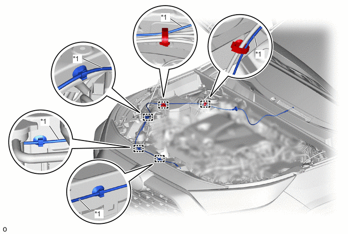
| *1 | Hood Lock Control Cable Assembly | - | - |
Remove the string.
53875A
2.INSTALL FRONT FENDER LINER RH
75601A
3.INSTALL FRONT FENDER MOULDING SUB-ASSEMBLY RH (for Off Road Package)
- HINT:
-
Use the same procedure described for the LH side.
-
Click hereVehicle Exterior>EXTERIOR PANELS / TRIM>WHEEL OPENING MOULDING (for Front)>INSTALLATION
75601A
4.INSTALL FRONT FENDER MOULDING SUB-ASSEMBLY RH (except Off Road Package)
- HINT:
-
Use the same procedure described for the LH side.
-
Click hereVehicle Exterior>EXTERIOR PANELS / TRIM>WHEEL OPENING MOULDING (for Front)>INSTALLATION
51441
5.INSTALL NO. 1 ENGINE UNDER COVER
for A25A-FKS:
Click hereEngine / Hybrid System>A25A-FKS (ENGINE MECHANICAL)>ENGINE ASSEMBLY>INSTALLATION
for M20A-FKS:
Click hereEngine / Hybrid System>M20A-FKS (ENGINE MECHANICAL)>ENGINE ASSEMBLY>INSTALLATION
for A25A-FXS:
Click hereEngine / Hybrid System>A25A-FXS (ENGINE MECHANICAL)>ENGINE ASSEMBLY>INSTALLATION
for A25B-FXS:
Click hereEngine / Hybrid System>A25B-FXS (ENGINE MECHANICAL)>ENGINE ASSEMBLY>INSTALLATION
76621D
6.INSTALL FRONT FENDER MUDGUARD RH (w/ Mudguard)
- HINT:
-
Use the same procedure described for the LH side.
-
Click hereVehicle Exterior>EXTERIOR PANELS / TRIM>MUDGUARD>INSTALLATION
53895B
7.INSTALL FRONT FENDER FRONT SPLASH SHIELD RH (for Short Type)
53895B
8.INSTALL FRONT FENDER FRONT SPLASH SHIELD RH (for Long Type)
9.INSTALL FRONT WHEEL
53601
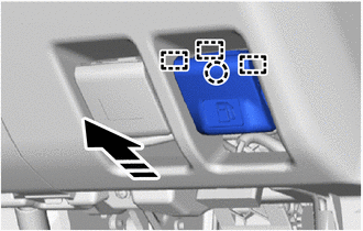
10.INSTALL HOOD LOCK CONTROL LEVER SUB-ASSEMBLY
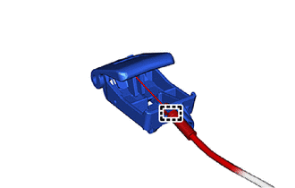
Connect the hood lock control cable assembly to the hood lock control lever sub-assembly.
Attach the clamp.
|
|
Install in this Direction |
Attach the guide and claw and install the hood lock control lever sub-assembly in the direction indicated by the arrow shown in the illustration.
53510
11.INSTALL HOOD LOCK ASSEMBLY
Apply MP grease to the sliding areas of the hood lock assembly.
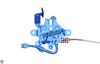
Attach the clamp and connect the hood lock control cable assembly.
- NOTICE:
-
Do not bend the hood lock control cable assembly excessively.
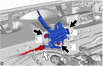

|
Bolt |

|
Connector |
Install the hood lock assembly with the 3 bolts in the order shown in the illustration.
- Torque:
- 8.0 N*m (82 kgf*cm, 71 in.*lbf)
w/ Courtesy Switch:
Connect the connector.
17750A
12.INSTALL AIR CLEANER INLET ASSEMBLY (for Gasoline Model)
53301
13.INSPECT FITTING OF HOOD SUB-ASSEMBLY