STEERING GEAR / LINKAGE STEERING GEAR INSTALLATION
PROCEDURE

 44250
1.INSTALL POWER STEERING GEAR ASSEMBLY
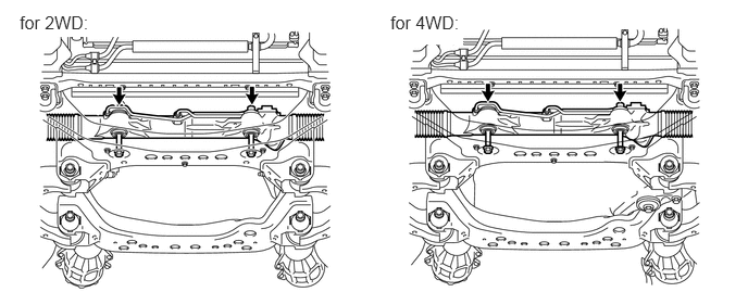
Install the power steering gear with the 2 bolts and 2 nuts.
- Torque:
- 120 N*m (1224 kgf*cm, 89 ft.*lbf)
44410
2.INSTALL PRESSURE FEED TUBE ASSEMBLY
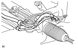
Temporarily connect the pressure feed tube to the power steering gear.
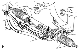
Install the pressure feed tube clamp with the 2 bolts.
- Torque:
- 28 N*m (286 kgf*cm, 21 ft.*lbf)
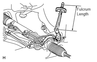
Using a union nut wrench, tighten the pressure feed tube (pressure feed tube side).
- Torque:
- 25 N*m (255 kgf*cm, 18 ft.*lbf)
- NOTICE:
-
Use the formula calculate special torque values for situations for situations where a union nut wrench is combined with a torque wrench (See page General>INTRODUCTION>REPAIR INSTRUCTION>PRECAUTION).
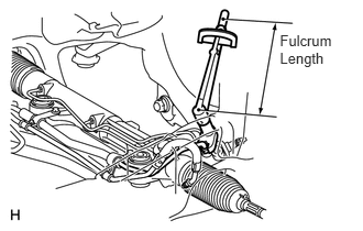
Using a union nut wrench, tighten the pressure feed tube (return tube side).
- Torque:
- 25 N*m (255 kgf*cm, 18 ft.*lbf)
- NOTICE:
-
Use the formula calculate special torque values for situations for situations where a union nut wrench is combined with a torque wrench (See page General>INTRODUCTION>REPAIR INSTRUCTION>PRECAUTION).
45047
3.CONNECT TIE ROD END SUB-ASSEMBLY LH
Connect the tie rod end LH to the steering knuckle with the nut.
- Torque:
- 69 N*m (704 kgf*cm, 51 ft.*lbf)
Install a new cotter pin.
- HINT:
-
Further tighten the nut up to 60° if the holes for the cotter pin are not aligned.
45046
4.CONNECT TIE ROD END SUB-ASSEMBLY RH
- HINT:
-
Use the same procedures described for the LH side.
45203
5.CONNECT NO. 2 STEERING INTERMEDIATE SHAFT SUB-ASSEMBLY
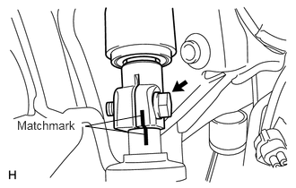
Align the matchmarks on the No. 2 steering intermediate shaft and power steering gear.
Install the bolt.
- Torque:
- 35 N*m (360 kgf*cm, 26 ft.*lbf)
6.INSTALL ENGINE ASSEMBLY
for 3UR-FE:
Install engine assembly (See page Engine / Hybrid System>3UR-FE ENGINE MECHANICAL>ENGINE ASSEMBLY>INSTALLATION).
for 3UR-FBE:
Install engine assembly (See page Engine / Hybrid System>3UR-FBE ENGINE MECHANICAL>ENGINE ASSEMBLY>INSTALLATION).
7.INSTALL FRONT WHEEL
- Torque:
- for Aluminum Wheel : 131 N*m (1336 kgf*cm, 97 ft.*lbf)
- for Steel Wheel : 209 N*m (2131 kgf*cm, 154 ft.*lbf)
8.BLEED POWER STEERING FLUID
9.CHECK POWER STEERING FLUID LEVEL
10.INSPECT FOR POWER STEERING FLUID LEAK
11.PLACE FRONT WHEELS FACING STRAIGHT AHEAD
- HINT:
-
Perform this procedure with the front of the vehicle jacked up.
12.ADJUST FRONT WHEEL ALIGNMENT
Adjust the front wheel alignment (See page Suspension>ALIGNMENT / HANDLING DIAGNOSIS>FRONT WHEEL ALIGNMENT>ADJUSTMENT).