Home › Vehicle Exterior › WINDOW / GLASS › WINDOW DEFOGGER SYSTEM
RM27L0U _59 Vehicle Exterior _049347 WINDOW / GLASS _0235941 WINDOW DEFOGGER SYSTEM J

WINDOW / GLASS  WINDOW DEFOGGER SYSTEM  Rear Window Defogger System does not Operate  


DESCRIPTION

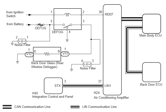
When the defogger switch in the integration control and panel is turned on, the air conditioning amplifier checks that the back door window is in the fully closed position, turns on the DEFOG relay, and then activates the rear window defogger.

HINT:
·

The rear window defogger and rear wiper will not operate if the back door power window is not initialized.

·

The back door window fully closed position signal is transmitted from the back door ECU to the main body ECU via LIN communication, and from the main body ECU to the air conditioning amplifier via CAN communication.


WIRING DIAGRAM
B191461E03
0.27,0.433 1.085,0.780 0.815,0.347 10 from Ignition Switch 0.286,0.947 1.121,1.143 0.835,0.195 10 from Battery 0.632,1.848 1.378,2.036 0.746,0.189 10 Noise Filter 0.682,1.525 0.791,1.700 0.109,0.175 10 2 1.148,1.525 1.284,1.687 0.136,0.162 10 1 1.476,2.12 1.625,2.296 0.149,0.175 10 E 2.494,2.12 2.630,2.282 0.136,0.162 10 B 2.185,0.425 2.323,0.579 0.137,0.154 10 1 3.565,0.425 3.681,0.587 0.116,0.162 10 2 3.565,0.826 3.705,0.995 0.140,0.169 10 3 2.961,1.279 3.114,1.448 0.152,0.169 10 4 2.185,0.826 2.295,0.995 0.109,0.169 10 5 2.246,1.289 2.792,1.428 0.546,0.139 10 DEFOG 3.452,2.857 4.198,3.046 0.746,0.189 10 Noise Filter 3.502,2.534 3.611,2.709 0.109,0.175 10 4 3.967,2.534 4.103,2.696 0.136,0.162 10 3 2.703,2.216 2.977,2.365 0.273,0.149 10 V11 1.129,2.24 1.437,2.396 0.309,0.156 10 V12 2.773,2.021 2.909,2.183 0.136,0.162 10 1 1.209,2.049 1.345,2.211 0.136,0.162 10 1 1.35,2.628 2.918,3.008 1.567,0.380 10 Back Door Glass (Rear Window Defogger) 1.391,4.07 3.254,4.252 1.863,0.182 10 Integration Control and Panel 4.256,0.431 4.438,0.583 0.182,0.152 10 38 4.526,0.53 4.942,0.682 0.416,0.152 10 RDEF 2.77,3.412 2.876,3.551 0.105,0.139 10 3 2.352,3.604 2.660,3.757 0.308,0.152 10 STX 4.233,3.421 4.430,3.579 0.197,0.157 10 37 4.514,3.607 4.827,3.770 0.314,0.163 10 LIN1 4.05,4.116 5.677,4.284 1.628,0.168 10 Air Conditioning Amplifier 6.05,3.553 7.079,3.702 1.029,0.148 10 Back Door ECU 6.016,1.437 7.045,1.600 1.029,0.163 10 Main Body ECU 0.544,4.51 2.268,4.680 1.724,0.170 10 : CAN Communication Line 3.48,4.51 5.203,4.680 1.724,0.170 10 : LIN Communication Line 1.391,3.926 1.688,4.080 0.296,0.154 10 H45 4.05,3.907 4.329,4.072 0.279,0.165 10 H24 1.513,1.126 2.054,1.287 0.540,0.161 10 DEFOG

PROCEDURE

1.PERFORM INITIALIZATION (BACK DOOR POWER WINDOW)
a.

Initialize the back door power window regulator motor (See page Vehicle Exterior>WINDOW / GLASS>POWER WINDOW CONTROL SYSTEM>INITIALIZATION)


b.

Check if rear window defogger function operate (See page Vehicle Exterior>WINDOW / GLASS>WINDOW DEFOGGER SYSTEM>OPERATION CHECK)

OK:

Rear window defogger function operates.


OK

END

NG

2.CHECK LIN COMMUNICATION SYSTEM
a.

Check for LIN communication system DTCs related to the power window control system (See page Power Source / Network>NETWORKING>LIN COMMUNICATION SYSTEM>DTC CHECK / CLEAR).

OK:

LIN communication system DTCs are not output.


OK

3.CHECK CAN COMMUNICATION SYSTEM

NG

3.CHECK CAN COMMUNICATION SYSTEM
a.

Check for CAN communication system DTCs (See page Power Source / Network>NETWORKING>CAN COMMUNICATION SYSTEM>DIAGNOSIS SYSTEM).

OK:

CAN communication system DTCs are not output.


OK

4.PERFORM ACTIVE TEST USING TECHSTREAM (DEFOG RELAY)

NG

4.PERFORM ACTIVE TEST USING TECHSTREAM (DEFOG RELAY)
a.

Connect the Techstream to the DLC3.


b.

Turn the ignition switch to ON.


c.

Turn the Techstream on.


d.

Enter the following menus: Body Electrical / Air Conditioner / Active Test / Defogger Relay (Rear)


e.

Check that the defogger operation.

Air Conditioner
Tester Display Test Part Control Range Diagnostic Note
Defogger Relay (Rear) Rear window defogger relay operation OFF or ON -

OK:

Defogger operates on and off.


OK

5.CHECK AIR CONDITIONING SYSTEM (LIN COMMUNICATION)

NG

8.CHECK HARNESS AND CONNECTOR (DEFOG RELAY - BACK DOOR GLASS [REAR WINDOW DEFOGGER])
5.CHECK AIR CONDITIONING SYSTEM (LIN COMMUNICATION)
a.

Operate the front air conditioner control panel to change the set temperature and check that the temperature at the outlets changes.

OK:

The outlet temperature changes in accordance with the operation of the control panel.


OK

6.REPLACE INTEGRATION CONTROL AND PANEL

NG

6.REPLACE INTEGRATION CONTROL AND PANEL
a.

Temporarily replace the integration control and panel with a new or normally functioning one (See page Vehicle Interior>HEATING / AIR CONDITIONING>AIR CONDITIONING PANEL>REMOVAL).


NEXT

7.CHECK INTEGRATION CONTROL AND PANEL (OPERATION)
a.

Check that the malfunction disappears.

OK:

Malfunction disappears.


OK

END (INTEGRATION CONTROL AND PANEL IS DEFECTIVE)

NG

8.CHECK HARNESS AND CONNECTOR (DEFOG RELAY - BACK DOOR GLASS [REAR WINDOW DEFOGGER])
a.
U153254E02
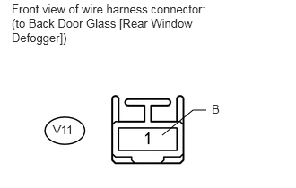
1.885,1.573 2.24,1.281 2.24,1.281 2.396,1.281 false 0.135,0.021 2.417,0.563 2.281,0.542 10 false Front view of wire harness connector: (to Back Door Glass [Rear Window Defogger]) 0.615,1.427 0.885,1.594 0.271,0.167 10 false V11 2.458,1.188 2.594,1.365 0.135,0.177 10 false B

Disconnect the V11 rear defogger connector.


b.

Measure the voltage according to the value(s) in the table below.

Standard Voltage:
Tester Connection Switch Condition Specified Condition
V11-1 (B) - Body ground Engine running
Rear defogger switch ON
11 to 14 V


c.

Reconnect the rear defogger connector.


OK

9.CHECK HARNESS AND CONNECTOR (REAR WINDOW DEFOGGER - BODY GROUND)

NG

10.INSPECT FUSE (DEFOG)
9.CHECK HARNESS AND CONNECTOR (REAR WINDOW DEFOGGER - BODY GROUND)
a.
U153255E01
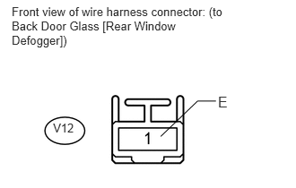
0.136,0.055 2.580,0.602 2.444,0.547 10 Front view of wire harness connector: (to Back Door Glass [Rear Window Defogger]) 0.616,1.404 0.941,1.569 0.325,0.165 10 V12 1.866,1.587 2.293,1.176 2.293,1.176 2.507,1.176 false 2.53,1.084 2.682,1.261 0.153,0.177 12 E

Disconnect the V12 rear defogger connector.


b.

Measure the resistance according to the value(s) in the table below.

Standard Resistance:
Tester Connection Condition Specified Condition
V12-1 (E) - Body ground Always Below 1 Ω


c.

Reconnect the rear defogger connector.


OK

REPAIR OR REPLACE BACK DOOR GLASS (REAR WINDOW DEFOGGER)

NG

REPAIR OR REPLACE HARNESS OR CONNECTOR

10.INSPECT FUSE (DEFOG)
a.
B191460E04
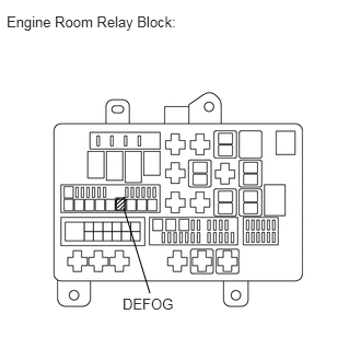
1.104,1.885 1.188,2 0.083,0.115 1.104,1.917 1.135,1.885 false 1.094,1.958 1.188,1.875 false 1.115,1.979 1.208,1.896 false 1.146,1.99 1.188,1.948 false 1.177,1.979 1.427,2.792 false 0.063,0.125 1.802,0.302 1.74,0.177 10 false Engine Room Relay Block: 1.167,2.813 1.708,2.979 0.542,0.167 10 false DEFOG

Remove the DEFOG fuse from the engine room relay block.


b.

Measure the resistance according to the value(s) in the table below.

Standard Resistance:
Tester Connection Condition Specified Condition
DEFOG fuse Always Below 1 Ω


c.

Reinstall the DEFOG fuse.


OK

11.INSPECT DEFOG RELAY

NG

REPLACE FUSE

11.INSPECT DEFOG RELAY
a.
B106753E17
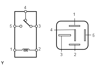
2.49,0.844 2.49,0.615 false 2.854,1.177 3.042,1.177 false 2.5,1.5 2.5,1.719 false 2.052,1.208 2.052,1.74 false 2.479,1 1.802,1.01 false 0.802,0.167 0.896,0.365 0.094,0.198 10 false 4 0.323,0.792 0.417,0.99 0.094,0.198 10 false 5 1.281,0.792 1.375,0.99 0.094,0.198 10 false 3 0.333,1.573 0.427,1.771 0.094,0.198 10 false 1 1.281,1.563 1.375,1.76 0.094,0.198 10 false 2 1.677,0.917 1.771,1.115 0.094,0.198 10 false 4 3.083,1.104 3.177,1.302 0.094,0.198 10 false 5 2.01,1.75 2.104,1.948 0.094,0.198 10 false 3 2.438,0.396 2.531,0.594 0.094,0.198 10 false 1 2.469,1.75 2.563,1.948 0.094,0.198 10 false 2

Remove the DEFOG relay from the engine room relay block.


b.

Measure the resistance according to the value(s) in the table below.

Standard Resistance:
Tester Connection Condition Specified Condition
3 - 4 When battery voltage is not applied between terminals 1 and 2 Below 1 Ω
3 - 5 10 kΩ or higher
3 - 4 When battery voltage is applied to terminals 1 and 2 10 kΩ or higher
3 - 5 Below 1 Ω


c.

Reinstall the DEFOG relay.


OK

12.CHECK HARNESS AND CONNECTOR (DEFOG RELAY - BATTERY)

NG

REPLACE DEFOG RELAY

12.CHECK HARNESS AND CONNECTOR (DEFOG RELAY - BATTERY)
B191462E03
1.146,4.281 0.906,4.281 0.906,4.281 0.802,3.906 false 0.135,0 2.438,0.354 2.302,0.354 10 false Component without relay connected: (Engine Room Relay Block) 1.208,4.198 2.115,4.406 0.906,0.208 10 false DEFOG Relay

a.

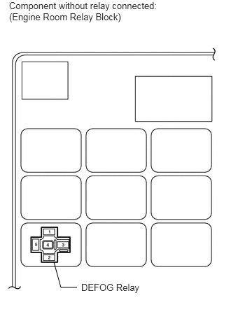
Remove the DEFOG relay from the engine room relay block.


b.

Measure the voltage according to the value(s) in the table below.

Standard Voltage:
Tester Connection Switch Condition Specified Condition
DEFOG relay terminal 1 - Body ground Ignition switch ON 11 to 14 V
DEFOG relay terminal 5 - Body ground Always 11 to 14 V


c.

Reinstall the DEFOG relay.


OK

13.CHECK HARNESS AND CONNECTOR (DEFOG RELAY - AIR CONDITIONING AMPLIFIER)

NG

REPAIR OR REPLACE HARNESS OR CONNECTOR

13.CHECK HARNESS AND CONNECTOR (DEFOG RELAY - AIR CONDITIONING AMPLIFIER)
B443148E01
4.552,2.75 4.906,2.927 0.354,0.177 0.927,3.344 1.073,3.521 1.073,3.521 1.354,3.521 false 4.896,3.25 5.073,3.25 5.073,3.25 5.219,2.854 true 0.198,0.031 2.427,0.375 2.229,0.344 10 false Component without relay connected: (Engine Room Relay Block) 4.271,0.292 6.594,0.646 2.323,0.354 10 false Rear view of wire harness connectors: (to Air Conditioning Amplifier) 1.406,3.438 2.323,3.615 0.917,0.177 10 false DEFOG Relay 4.49,3.177 4.875,3.354 0.385,0.177 10 false RDEF 4.604,2.76 4.875,2.927 0.271,0.167 10 false H24

a.

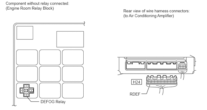
Remove the DEFOG relay from the engine room relay block.


b.

Disconnect the H24 air conditioning amplifier connector.


c.

Measure the resistance according to the value(s) in the table below.

Standard Resistance:
Tester Connection Condition Specified Condition
DEFOG relay terminal 2 - H24-38 (RDEF) Always Below 1 Ω


d.

Reconnect the air conditioning amplifier connector.


e.

Reinstall the DEFOG relay.


OK

14.CHECK HARNESS AND CONNECTOR (REAR WINDOW DEFOGGER - DEFOG RELAY, BODY GROUND)

NG

REPAIR OR REPLACE HARNESS OR CONNECTOR

14.CHECK HARNESS AND CONNECTOR (REAR WINDOW DEFOGGER - DEFOG RELAY, BODY GROUND)
B443149E01
4.656,1.979 5.021,2.208 0.365,0.229 4.667,2.333 5.031,2.563 0.365,0.229 1.156,3.323 1.385,3.542 1.385,3.542 1.583,3.542 false 0.177,0.042 2.406,0.396 2.229,0.354 10 true Component without relay connected: (Engine Room Relay Block) 1.646,3.469 2.563,3.667 0.917,0.198 10 true DEFOG Relay 4.521,0.385 6.792,0.76 2.271,0.375 10 true Front view of wire harness connector: (to Rear Window Defogger) 4.698,2.01 4.958,2.177 0.26,0.167 10 false V11 4.719,2.365 4.979,2.531 0.26,0.167 10 false V12

a.

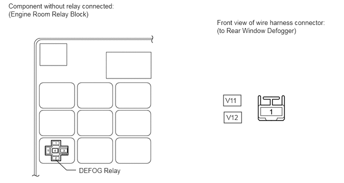
Disconnect the V11 and V12 defogger connectors.


b.

Remove the DEFOG relay from the engine room relay block.


c.

Measure the resistance according to the value(s) in the table below.

Standard Resistance:
Tester Connection Condition Specified Condition
V11-1 (B) - DEFOG relay terminal 3 Always Below 1 Ω
V12-1 (E) - Body ground Always Below 1 Ω
DEFOG relay terminal 4 - Body ground Always Below 1 Ω
V11-1 (B) - Body ground Always 10 kΩ or higher


d.

Reinstall the DEFOG relay .


e.

Reconnect the defogger connectors.


OK

NG

REPAIR OR REPLACE HARNESS OR CONNECTOR