BRAKE CONTROL / DYNAMIC CONTROL SYSTEMS BRAKE ACTUATOR INSTALLATION
PROCEDURE

 1.INSTALL SKID CONTROL ECU ASSEMBLY
- NOTICE:
- ·
Do not clean the sealing surface with compressed air, chemical solvents or sharp-edged objects.
·Do not touch or clean the pressure sensor contacts with your fingers.
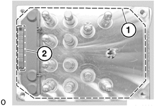
Clean the sealing surface (1) if necessary, with a lint-free cloth.
Ensure that the contacts (2) are not damaged.
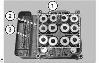
For renewed use of the brake actuator assembly, an add-on skid control ECU assembly repair kit is required.
- HINT:
-
The repair kit contains a new silicone seal (1) and bolts.
Make sure that the valve coils (2) are not damaged.
- NOTICE:
- ·
Do not clean, readjust or touch the valve coils with your fingers.
·If damaged, replace the skid cntrol ECU assembly (3).
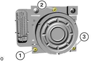
Connect skid control ECU assembly carefully to brake actuator assembly.
Replace T25 bolts (1) to (3).
Tighten T25 bolts (1) to (3) in this order in stages.
- Torque:
- 5.5 N*m (56 kgf*cm, 49 in.*lbf)
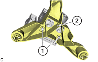
Install brake actuator bracket assembly (2).
Replace T25 screws (1).
Insert T25 screws (1) and tighten.
- Torque:
- 8.0 N*m (82 kgf*cm, 71 in.*lbf)
2.INSTALL BRAKE ACTUATOR WITH BRACKET
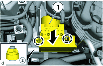
Insert the brake actuator with bracket (1) into the bracket (2) towards the bottom.
Tighten bolt.
- Torque:
- 8.0 N*m (82 kgf*cm, 71 in.*lbf)
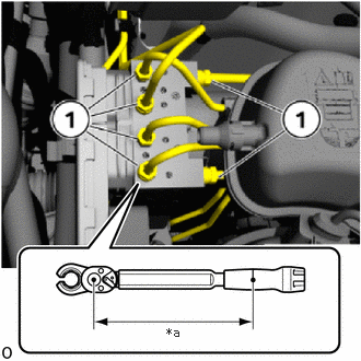
| *a | Torque Wrench Fulcrum Length |
Tighten the 11 mm and 12 mm union nuts of the brake lines.
- SST
- 09700-WA070
- Torque:
- Specified tightening torque : 17 N*m (173 kgf*cm, 13 ft.*lbf)
- HINT:
-
Calculate the torque wrench reading when changing the fulcrum length of the torque wrench.
-
Click hereGeneral>INTRODUCTION>REPAIR INSTRUCTION>PRECAUTION
Connect connectors and lock.
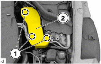
Install the engine room ECU cover (2).
- HINT:
-
The snap-lock couplings (1) must engage audibly.
3.REMOVE BRAKE PEDAL PRESSURE
Remove the brake pedal pressure.
16470
4.INSTALL RADIATOR RESERVE TANK ASSEMBLY
16482
5.INSTALL RADIATOR RESERVE TANK SUB-ASSEMBLY
6. BLEED BRAKE LINE
53879
7.INSTALL FRONT FENDER LINER LH
8.INSTALL FRONT WHEEL
9. PERFORMING THE START-UP OF THE DSC UNIT AND ADJUSTMENT OF THE SENSORS FOR DRIVING
Connect the diagnosis system to the vehicle and enter the following menus:
Vehicle management / Service functions / Chassis / Traction control system / DSC control unit adjustment / ABL DSC control unit adjustment
Vehicle management / Service functions / Chassis / Traction control system / Adjustment of the driving dynamics sensors / ABL Adjustment of the driving dynamics sensors