FRONT SUSPENSION FRONT SHOCK ABSORBER REMOVAL
CAUTION / NOTICE / HINT
- CAUTION:
- ·
Vehicle may slip off the vehicle hoist if the vehicle hoist is handled incorrectly.
Danger! Life-threatening injuries!
-Observe safety information on raising the vehicle using a vehicle hoist.
-For additional information see:
Click hereGeneral>INTRODUCTION>REPAIR INSTRUCTION>VEHICLE LIFT AND SUPPORT LOCATIONS
·Spring preload.
Danger of injury!
-The use of the specified special tool (tool) is mandatory.
-The described operation must be carried out properly.
- HINT:
- ·
Use the same procedure for the RH side and LH side.
·The following procedure is for the LH side.
PROCEDURE

 1.REMOVE FRONT WHEEL
53896B
2.REMOVE FRONT FENDER SPLASH FRONT SHIELD
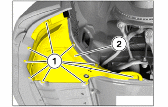
Loosen screws (1).
Feed out the front fender splash front shield (2) to the side.
53879
3.REMOVE FRONT FENDER LINER
53876F
4.REMOVE FRONT NO. 2 FENDER LINER
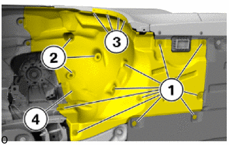
Loosen screws (1).
Loosen nuts (2).
Release the plastic rivet (3) and remove the front No. 2 fender liner (4).
89516F
5.SEPARATE FRONT SKID CONTROL SENSOR WIRE
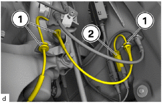
Detach the front skid control sensor wire from the brackets (1).
Unlock the plug connection (2) and disconnect.
6.SEPARATE FRONT FLEXIBLE HOSE
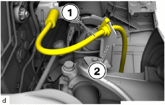
Release the front flexible hose (1) from the bracket (2).
7.REMOVE FRONT BRAKE DISC (for 4-Pot Caliper)
8.REMOVE FRONT BRAKE DISC (except 4-Pot Caliper)
9.DISCONNECT SENSOR WIRE (w/ AVS)
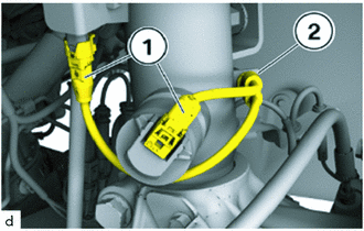
Unlock and disconnect the plug connections (1).
Detach the sensor wire from the holder (2).
48810
10.SEPARATE FRONT STABILIZER LINK ASSEMBLY
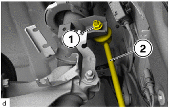
Loosen the 16 mm nut (1), if necessary, counter-hold the T30 "TORX" socket wrench.
Release the front stabilizer link assembly (2) from the front shock absorber assembly.
45047
11.DISCONNECT TIE ROD END SUB-ASSEMBLY
12.SEPARATE FRONT LOWER SUSPENSION ARM ASSEMBLY
- NOTICE:
- ·
Component damage caused by striking tools.
Brute force can result in component damage.
-Only use those tools intended for the work.
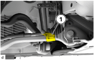
for LH Side:
Release the front height control sensor link sub-assembly (1) from the front lower suspension arm assembly.
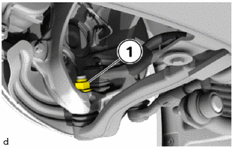
Loosen the nut (1), if necessary, counter-hold the T40 "TORX" socket wrench.
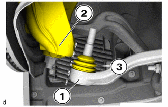
Make sure that the front lower suspension arm assembly (1) is not in contact with the steering knuckle (2).
- NOTICE:
- ·
Otherwise, the rubber grommet (3) can be damaged. The components must not be touching.
·The rubber grommet (3) may be damaged by the steering knuckle (2).
48630
13.SEPARATE FRONT UPPER SUSPENSION ARM ASSEMBLY
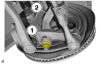
Loosen the nut (1), if necessary, counter-hold the T40 "TORX" socket wrench.
Release the front upper suspension arm assembly (2) from the steering knuckle.
55878B
14.REMOVE COWL VENT COVER LH (for LH Side)
55877B
15.REMOVE COWL VENT COVER RH (for RH Side)
53867
16.REMOVE FRONT FENDER TO COWL SIDE SEAL
17.REMOVE FRONT SHOCK ABSORBER WITH COIL SPRING
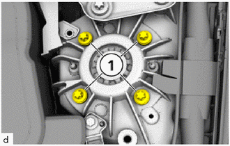
Loosen the bolts (1).
Remove the front shock absorber with coil spring towards the bottom.
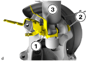
Release the 16 mm nut (1) and 18 mm bolt (2).
Remove the holder (3).
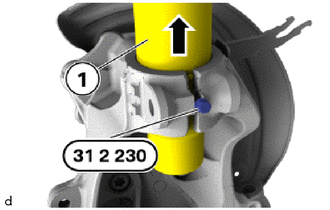
Spread the steering knuckle with the special tool 0 494 541 (31 2 230).
- SST
- 09600-WA030
Pull the front shock absorber with coil spring (1) from the steering knuckle in the direction of the arrow.
18.REMOVE FRONT COIL SPRING
- NOTICE:
- ·
Damage of the front coil spring.
Any use of faulty protections leads to front coil spring damage. Faulty protections may lead to a cracked front coil spring (corrosion).
-Check the protection for wear or damage and if necessary, replace the protections.
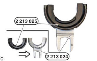
Mount special tool 2 213 025 on special tool 2 213 024.
- SST
- 09700-WA230
09700-WA240
- NOTICE:
-
The plate must be used with the protection.
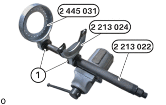
Clamp special tool 2 213 022 (31 3 340) into the vise.
- SST
- 09700-WA190
Position special tools 2 445 031 and 2 213 024 (31 3 351) from above on special tool 2 213 022 (31 3 340) until the locking bolts (1) engage tactilely and audibly.
- SST
- 09700-WA230
09700-WA260
- HINT:
-
Check positions of special tools 2 445 031 and 2 213 024 (31 3 351), and correct if necessary.
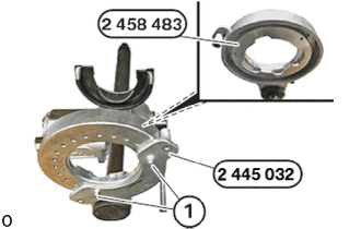
Position centering mount 2 458 483 in the mounting plate.
- SST
- 09700-WA220
Position counter holder 2 445 032 on the mounting plate.
- SST
- 09700-WA260
- HINT:
-
The parts will be screwed together via holes 5 and 11.
Turn centering mount 2 458 483 until the counter holder 2 240 486 can be attached by screws in the specified position.
Install and hand-tighten the screws (1) into the specified holes to attach counter holder 2 240 486 to the centering mount 2 458 483.
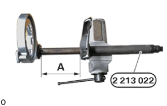
Set special tool 2 213 022 (31 3 340) to dimension (A).
- Dimension (A):
220 mm (8.66 in.)
Clean away any dirt or foreign matter from the front coil spring.
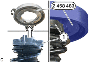
Insert front shock absorber with coil spring into spring tensioner and position front suspension support sub-assembly (1) on centering mount 2 458 483.
- SST
- 09700-WA220
The front suspension support sub-assembly (1) must rest completely on the centering mount 2 458 483, if necessary, tighten the spring tensioner by hand.
- NOTICE:
-
The lower turn of the front coil spring must lie completely in the recess of the special tool 2 240 516.
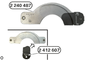
The plate 2 240 487 must be used with the protection 2 412 607.
- SST
- 09700-WA200
09700-WA210
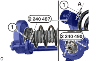
Position the plate 2 240 487 with the screws 2 240 490.
- SST
- 09700-WA200
- NOTICE:
-
The rubberized side of the plate 2 240 487 must rest against the upper turn of the front coil spring.
Position the front shock absorber with coil spring so that the front coil spring end (1) protrudes with dimension (A) on the plate 2 240 487.
- Dimension (A):
5.0 mm (0.197 in.)
Tighten screws 2 240 490 evenly.
- Torque:
- 8.0 N*m (82 kgf*cm, 71 in.*lbf)
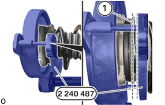
plate 2 240 487 must rest parallel to (1) the upper turn of the front coil spring.
- NOTICE:
- ·
The clamping process must be stopped immediately if the front coil spring end begins to rotate relative to the plate 2 240 487.
·The correct seating of the plate 2 240 487 must be checked and the rubberized protection and the plate 2 240 487 checked for wear.
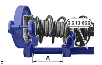
Apply tension to the front coil spring until dimension (A) on special tool 2 213 022 (31 3 340) is reached.
- Dimension (A):
120 mm (4.72 in.)
- NOTICE:
-
It is imperative to ensure that dimension (A) is not undershot.
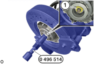
Release the front support to front shock absorber nut (1) with special tool 0 496 514 (33 0 040).
- SST
- 09700-WA250
- NOTICE:
-
Do not operate special tool with an impact wrench.
Feed front shock absorber with front lower coil spring insulator and front spring bumper out of the tensioned front coil spring and remove.
Relieve tension on front coil spring.
- NOTICE:
-
Do not operate special tool with an impact wrench.
Release spring tensioner.
48331C
19.REMOVE FRONT SPRING BUMPER
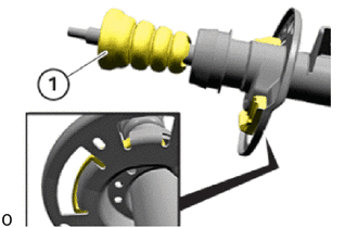
Remove the front spring bumper (1).
48158C
20.REMOVE FRONT LOWER COIL SPRING INSULATOR
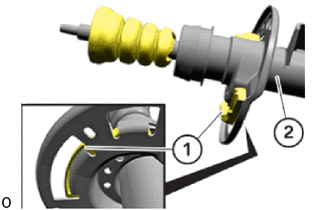
Remove front lower coil spring insulator (1) from the front shock absorber assembly (2).
48609
21.REMOVE FRONT SUSPENSION SUPPORT SUB-ASSEMBLY
- HINT:
-
Perform this procedure only when replacement of the front suspension support sub-assembly and front No. 1 shock absorber dust cover is necessary.
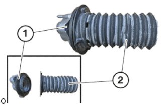
Pull down and remove front suspension support sub-assembly (1) from the front No. 1 shock absorber dust cover (2).