EXTERIOR PANELS / TRIM REAR BUMPER DISASSEMBLY
PROCEDURE

 64730C
1.REMOVE DECK TRIM SIDE BOARD AND DECK SIDE TRIM COVER RH
86240
2.REMOVE STEREO COMPONENT AMPLIFIER ASSEMBLY WITH BRACKET (w/ Stereo Component Amplifier)
81560
3.REMOVE REAR COMBINATION LIGHT ASSEMBLY LH
81550
4.REMOVE REAR COMBINATION LIGHT ASSEMBLY RH
- HINT:
-
Use the same procedure as for the LH side.
89342B
5.REMOVE REAR SIDE ULTRASONIC SENSOR
89342
6.REMOVE REAR CORNER ULTRASONIC SENSOR
- HINT:
-
Use the same procedure as for the rear side ultrasonic sensor.
89342A
7.REMOVE REAR CENTER ULTRASONIC SENSOR
89348A
8.REMOVE NO. 2 ULTRASONIC SENSOR RETAINER
81670A
9.REMOVE BACK-UP LIGHT ASSEMBLY
10.REMOVE TELEVISION CAMERA ASSEMBLY
11.REMOVE BRACKET FOR REAR VIEW CAMERA
81270
12.REMOVE LICENSE PLATE LIGHT ASSEMBLY
13.REMOVE REAR BUMPER PLATE RH
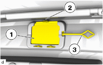
Disengage the claw (2).
Disengage the hook (3) to remove the rear bumper plate RH (1).
81920
14.REMOVE REFLEX REFLECTOR ASSEMBLY LH
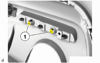
Remove the screws (1).
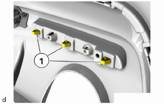
Disengage claws (1) to remove the reflex reflector assembly LH.
81910
15.REMOVE REFLEX REFLECTOR ASSEMBLY RH
- HINT:
-
Use the same procedure as for the LH side.
16.REMOVE NO. 1 REAR NAME PLATE
17.REMOVE NAME PLATE
18.REMOVE SYMBOL EMBLEM
19.REMOVE REAR BUMPER COVER LOWER SECTION
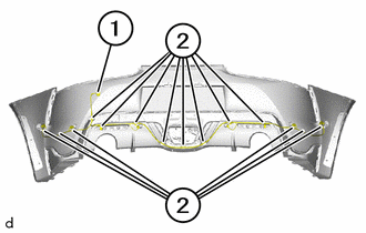
Disengage the clamps to remove the wiring harness (1).
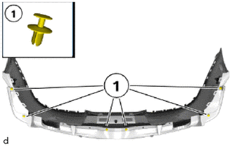
Remove the clips (1).
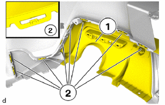
Disengage the claws (2).
- HINT:
-
Perform the operations on the left and right side.
Remove the rear bumper cover lower section (1).
20.REMOVE AIR INLET TRIM STRIP LH
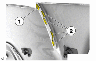
Disengage the claws (2) to remove the air inlet trim strip LH (1).
21.REMOVE AIR INLET TRIM STRIP RH
- HINT:
-
Use the same procedure as for the LH side.
52616B
22.REMOVE ABSORBER FUNNEL LH
52615C
23.REMOVE ABSORBER FUNNEL RH
- HINT:
-
Use the same procedure as for the LH side.
24.REMOVE BLIND SPOT MONITOR SENSOR LH
25.REMOVE BLIND SPOT MONITOR SENSOR RH
- HINT:
-
Use the same procedure as for the LH side.
26.REMOVE TELEVISION ANTENNA ASSEMBLY (w/ Digital terrestrial television)
27.REMOVE REAR BUMPER SIDE SUPPORT SUB-ASSEMBLY LH
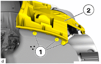
Remove the screws (1) on the rear bumper side support sub-assembly LH (2).
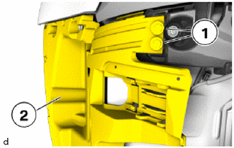
Remove the T20 screws (1) on the rear bumper side support sub-assembly LH (2).
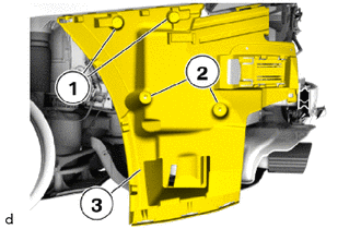
Remove the screws (1).
Remove the nuts (2).
Remove the rear bumper side support sub-assembly LH (3).
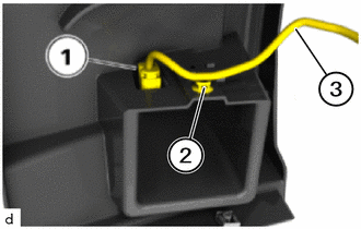
Disengage the clamp (2).
Disconnect the connector (1) and wiring harness (3) to remove the rear bumper side support sub-assembly LH.
28.REMOVE REAR BUMPER SIDE SUPPORT SUB-ASSEMBLY RH
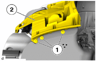
Remove the screws (1) on the rear bumper side support sub-assembly RH (2).
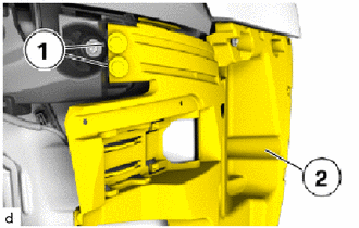
Remove the T20 screws (1) on the rear bumper side support sub-assembly RH (2).
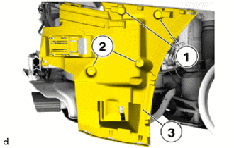
Remove the screws (1).
Remove the nuts (2).
Remove the rear bumper side support sub-assembly RH (3).
29.REMOVE NO. 1 REAR BUMPER SUPPORT
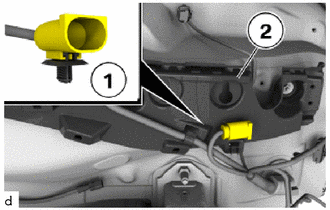
Disengage the clamp (1) to the guide for the No. 1 rear bumper support (2).
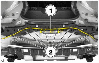
Disconnect the wiring harness (1) from the holders (2).
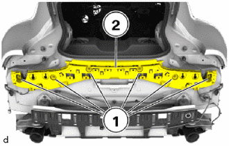
Remove the nuts (1) and guide for the No. 1 rear bumper support (2).
52615
30.REMOVE REAR BUMPER ENERGY ABSORBER
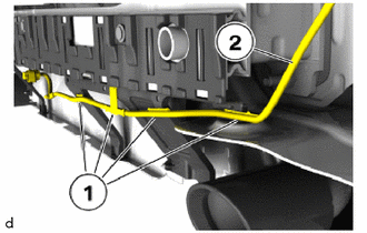
Disengage the clamps (1) to disconnect the wiring harness (2).
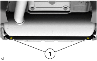
Remove the screws (1).
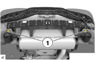
Remove the screws (1).
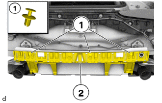
Remove the clips (1) and rear bumper energy absorber (2).
52023
31.REMOVE REAR BUMPER REINFORCEMENT SUB-ASSEMBLY
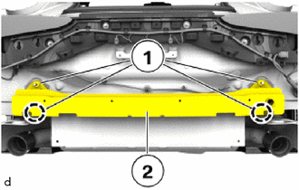
Using a deep socket wrench 18 mm, remove the 18 mm nuts (1).
Remove the rear bumper reinforcement sub-assembly (2).
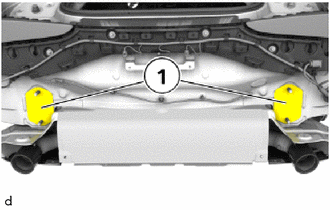
Remove the seals (1).