AUDIO / VIDEO STEREO COMPONENT AMPLIFIER INSTALLATION
PROCEDURE

 1.INSTALL STEREO COMPONENT AMPLIFIER ASSEMBLY
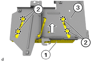

|
Install in this Direction |
Attach the guides (2) to install the stereo component amplifier assembly (1) to the No. 1 amplifier bracket (3) in the direction of the arrow.
Tighten bolt.
- Torque:
- 3.3 N*m (34 kgf*cm, 29 in.*lbf)
2.INSTALL STEREO COMPONENT AMPLIFIER ASSEMBLY WITH BRACKET
- NOTICE:
- ·
Damage to wires when disconnecting connectors and plug connections.
Sheared wires can cause a short circuit.
-Do not pull on the wires when disconnecting connectors and plug connections.
- ·
Sensitive optical fibers.
Damaged optical fibers can result in operating failure of the LED.
-Do not bend optical fibers too much and do not kink, as well. The minimum permissible bending radius is 25 mm.
-Avoid pressure and tensile loads and heat influences on the optical fiber.
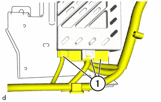
Connect connectors (1) and lock.
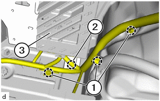
Attach the clamp (2) to install the stereo component amplifier assembly with bracket (3).
Attach the clamps (1).
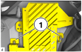
Tighten nuts (1).
- Torque:
- 6.0 N*m (61 kgf*cm, 53 in.*lbf)
64740B
3.INSTALL DECK TRIM SIDE BOARD AND DECK SIDE TRIM COVER LH
66311
4.INSTALL ROPE HOOK (w/ Courtesy Light)
81330
5.INSTALL NO. 1 LUGGAGE COMPARTMENT LIGHT ASSEMBLY
64716D
6.INSTALL DECK TRIM REAR COVER
81604
7.INSTALL TRIANGLE REFLECTOR SET
62609
8.INSTALL SEAT BELT HOLE COVER SUB-ASSEMBLY LH
64288D
9.INSTALL TRANSVERSE PIPE TRIM
62480A
10.INSTALL ROOF SIDE INNER GARNISH ASSEMBLY LH
11.CONNECT CABLE TO NEGATIVE BATTERY TERMINAL
B48 BATTERY
B58 BATTERY