B58 INTAKE / EXHAUST TURBOCHARGER INSTALLATION
PROCEDURE

 16027
1.INSTALL NO. 1 TURBO WATER PIPE SUB-ASSEMBLY
- HINT:
-
Perform this procedure only when replacement of the turbocharger sub-assembly is necessary.
Click hereEngine / Hybrid System>B58 (INTAKE / EXHAUST)>TURBO WATER PIPE (for Inlet Side)>INSTALLATION
15407
2.INSTALL INLET TURBO OIL PIPE SUB-ASSEMBLY
- HINT:
-
Perform this procedure only when replacement of the turbocharger sub-assembly is necessary.
Click hereEngine / Hybrid System>B58 (INTAKE / EXHAUST)>INLET TURBO OIL PIPE>INSTALLATION
16028
3.INSTALL NO. 2 TURBO WATER PIPE SUB-ASSEMBLY
- HINT:
-
Perform this procedure only when replacement of the turbocharger sub-assembly is necessary.
Click hereEngine / Hybrid System>B58 (INTAKE / EXHAUST)>TURBO WATER PIPE (for Outlet Side)>INSTALLATION
4.INSPECT THE COMPONENTS PRIOR TO INSTALLATION OF THE TURBOCHARGER SUB-ASSEMBLY
Check the outlet turbo oil pipe and inlet turbo oil pipe sub-assembly for contamination, obstruction and damage: clean or replace if necessary.
- HINT:
-
If the outlet turbo oil pipe and/or inlet turbo oil pipe sub-assembly are heavily contaminated, we recommend changing the engine oil and the oil filter.3
Check the No. 1 turbo water pipe sub-assembly and No. 2 turbo water pipe sub-assembly for the turbocharger sub-assembly for contamination, obstruction and damage: clean or replace if necessary.
Check all bolt connections and cable connections for correct fit.
Check air cleaner for contamination and clean or replace as needed.
Check correct functioning of ventilation hose.
17201
5.INSTALL TURBOCHARGER SUB-ASSEMBLY
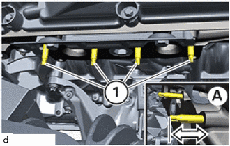
Check screw-in depth (A) of the E6 stud bolts (1); if necessary, screw the stud bolts in further or unscrew.
- NOTICE:
-
Secure the E6 stud bolts (1) with screw locking.
- Adhesive:
Screw Lock Loctite 273, High Strength
- Standard:
Dimension (A) = 30 mm (1.18 in.)
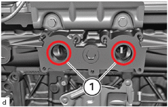
Clean sealing surfaces (1) on the exhaust manifold and on the cylinder head sub-assembly.
- NOTICE:
- ·
Damage to the surface.
·The use of metal-cutting tools (e.g. emery cloth) to clean the surfaces can damage them and lead to leaks or engine damage.
-Do not use any metal-cutting tools.
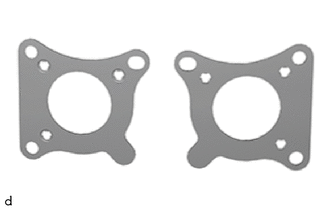
Replace exhaust manifold to head gaskets.
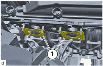
Position the exhaust manifold to head gaskets (1) on the cylinder head sub-assembly.
- HINT:
-
Make sure the exhaust manifold to head gaskets (1) are positioned correctly.
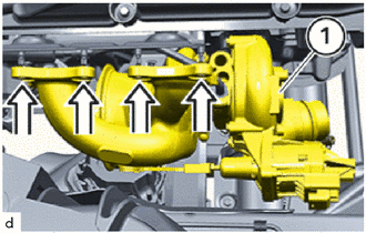
Install turbocharger sub-assembly (1) in the direction of the arrow.
- HINT:
-
Protect the turbocharger sub-assembly (1) from falling.
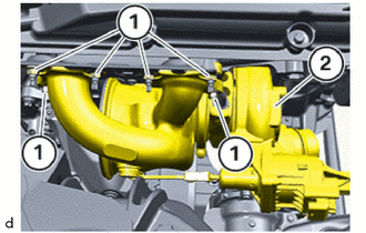
Replace the nuts on the turbocharger sub-assembly.
Tighten nuts.
- Torque:
- 18 N*m (184 kgf*cm, 13 ft.*lbf)
Replace the T40 bolt.
Tighten the T40 bolt on the turbocharger sub-assembly.
- Torque:
- 19 N*m (194 kgf*cm, 14 ft.*lbf)
Install the No. 1 turbo water pipe sub-assembly in the cylinder block sub-assembly and tighten the T30 bolt.
- Torque:
- 8.0 N*m (82 kgf*cm, 71 in.*lbf)
Tighten down the T30 bolt.
- Torque:
- 8.0 N*m (82 kgf*cm, 71 in.*lbf)
Fill turbocharger sub-assembly up to the top with engine oil using the inlet turbo oil pipe sub-assembly connection.
- Engine oil:
Toyota Genuine Motor Oil SN 0W-20 C5 for GR Toyota Supra
- HINT:
- ·
Technically suitable engine oils for BMW Group engines
·Observe the sign in the engine compartment! Only pour in approved engine oil with the correct SAE viscosity classification.
15407
6.CONNECT INLET TURBO OIL PIPE SUB-ASSEMBLY
Position turbo oil inlet pipe sub-assembly.
Tighten down the T30 bolt.
- Torque:
- 8.0 N*m (82 kgf*cm, 71 in.*lbf)
16028
7.CONNECT NO. 2 TURBO WATER PIPE SUB-ASSEMBLY
Tighten the T30 bolt on the holder of the No. 2 turbo water pipe sub-assembly.
- Torque:
- 8.0 N*m (82 kgf*cm, 71 in.*lbf)
Connect the coolant hose.
15474
8.INSTALL OUTLET TURBO OIL PIPE
25051
9.INSTALL EXHAUST MANIFOLD CONVERTER SUB-ASSEMBLY
17274
10.INSTALL COMPRESSOR INLET ELBOW
12261
11.INSTALL VENTILATION HOSE
17882
12.INSTALL NO. 2 AIR CLEANER HOSE
13.INSTALL EXHAUST PIPE ASSEMBLY
14.INSTALL STEERING LINK ASSEMBLY
15.CONNECT CABLE TO NEGATIVE BATTERY TERMINAL
16.ADD ENGINE COOLANT (for High Temperature)
17.INSPECT FOR COOLANT LEAK (for High Temperature)
18.INSPECT FOR EXHAUST GAS LEAK
19. CHECK ENGINE OIL LEVEL