B48 ENGINE MECHANICAL CYLINDER HEAD GASKET INSTALLATION
PROCEDURE

 11115
1.INSTALL CYLINDER HEAD GASKET
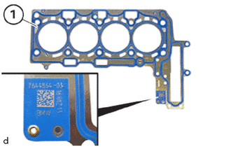
Install the cylinder head gasket (1).
11101
2.INSTALL CYLINDER HEAD SUB-ASSEMBLY
- HINT:
-
When replacing the cylinder head sub-assembly: The complete valve control and the Valvetronic servomotor are already pre-assembled for new cylinder head sub-assembly.
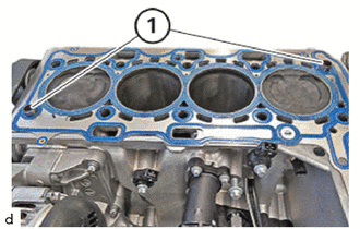
Check ring pins (1) for damage and correct mounting orientation and replace if necessary.
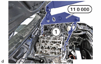
Install the cylinder head sub-assembly (1) and the turbocharger sub-assembly with the workshop crane and the special tool 0 490 561 (11 0 000).
- SST
- 09200-WA870
Fit new cylinder head T60 and E10 bolts.
Do not wash off bolt coating.
Lightly coat the contact surfaces of the screw heads with oil.
There must be no coolant, water and engine oil in any of the threaded holes in the engine block.
Position cylinder head sub-assembly.
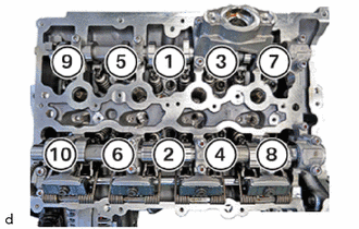
Tighten T60 bolts in the order (1) to (10).
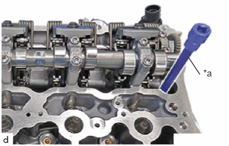
| *a | T60 Long "TORX" Socket Wrench |
Using a T60 deep "TORX" socket wrench, Tighten cylinder head sub-assembly T60 bolts using special tools 0 490 504 (00 9 120) in sequence (1) to (10).
- Torque:
- 30 N*m (306 kgf*cm, 22 ft.*lbf)
- SST
- 09900-WA010
Using SST, tighten the T60 bolts (1) to (10) an additional 90°.
- SST
- 09900-WA010
- HINT:
- ·
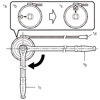 2.99,1.271 3.156,1.188 false 2.906,2.094 2.906,1.76 false 0.875,3 1.208,3 false 0.104,0.125 0.417,0.281 0.313,0.156 10 false *a 0.448,0.125 0.76,0.281 0.313,0.156 10 false *b 2.042,0.125 2.354,0.281 0.313,0.156 10 false *c 3.188,1.073 3.427,1.271 0.24,0.198 10 false *d 2.854,2.146 3.167,2.302 0.313,0.156 10 false *b 1.302,2.927 1.615,3.083 0.313,0.156 10 false *c
*a Example *b Before Tightening *c After Tightening *d Magnetic Portion
·The magnetic portion is used to secure the gauge to the vehicle.
·After first adjusting the needle of the gauge to 0°, tighten to the specified angle.
·Perform the work procedure carefully so that the gauge, etc. does not become tilted.
Using SST, tighten the T60 bolts (1) to (10) an additional 180°.
- SST
- 09900-WA010
- HINT:
- ·
2.99,1.271 3.156,1.188 false 2.906,2.094 2.906,1.76 false 0.875,3 1.208,3 false 0.104,0.125 0.417,0.281 0.313,0.156 10 false *a 0.448,0.125 0.76,0.281 0.313,0.156 10 false *b 2.042,0.125 2.354,0.281 0.313,0.156 10 false *c 3.188,1.073 3.427,1.271 0.24,0.198 10 false *d 2.854,2.146 3.167,2.302 0.313,0.156 10 false *b 1.302,2.927 1.615,3.083 0.313,0.156 10 false *c
*a Example *b Before Tightening *c After Tightening *d Magnetic Portion
·The magnetic portion is used to secure the gauge to the vehicle.
·After first adjusting the needle of the gauge to 0°, tighten to the specified angle.
·Perform the work procedure carefully so that the gauge, etc. does not become tilted.
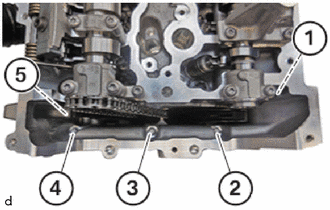
Tighten the E10 bolts (1) to (5).
- Torque:
- 20 N*m (204 kgf*cm, 15 ft.*lbf)
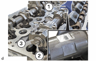
Secure the intake camshaft sub-assembly with an open-end spanner (1).
Position the camshaft sensor wheel (3).
Tighten down bolt (2).
- Torque:
- 8.0 N*m (82 kgf*cm, 71 in.*lbf)
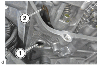
Feed in and install T45 bearing journal (1) on the No. 1 chain vibration damper (2).
Tighten the bearing journals (1).
- Torque:
- 20 N*m (204 kgf*cm, 15 ft.*lbf)
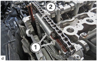
Install the chain damper guide (2).
Tighten the E10 bolts (1).
- Torque:
- 8.0 N*m (82 kgf*cm, 71 in.*lbf)
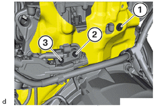
Position rear cylinder block cover.
Tighten the E8 bolts (2) to (3) and T30 bolt (1).
- Torque:
- 8.0 N*m (82 kgf*cm, 71 in.*lbf)
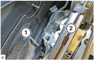
Clip in the transmission wire (1) in the highlighted area on the rear cylinder block cover (2).
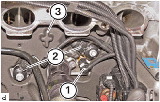
Position the No. 4 engine cover (3) correctly.
Connect connectors (1) and (2) and lock.
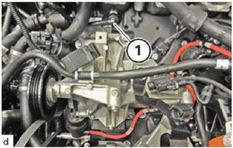
Connect and lock radiator reserve tank hose (1).
Lock must audibly engage.
3.ADJUST CAMSHAFT
13070A
4.INSTALL CAMSHAFT TIMING EXHAUST GEAR ASSEMBLY
13050
5.INSTALL CAMSHAFT TIMING GEAR ASSEMBLY
16020
6.INSTALL WATER PUMP ASSEMBLY
15474
7.INSTALL OUTLET TURBO OIL PIPE
25051
8.INSTALL EXHAUST MANIFOLD CONVERTER SUB-ASSEMBLY
9.ADD ENGINE COOLANT (for Low Temperature)
10.INSPECT FOR COOLANT LEAK (for Low Temperature)
51219
11.INSTALL FRONT SUSPENSION MEMBER LOWER PROTECTOR