B58 ENGINE MECHANICAL FRONT CRANKSHAFT OIL SEAL INSTALLATION
PROCEDURE

 1.INSTALL FRONT CRANKSHAFT OIL SEAL
- NOTICE:
- ·
Front crankshaft oil seal damage.
Touching the sealing lip (inner) and applying oil to the front crankshaft oil seal will lead to its destruction.
-Do not touch the sealing lip (inner) of the front crankshaft oil seal.
-Do not apply oil to the front crankshaft oil seal.
-Install the front crankshaft oil seal dry.
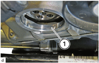
Clean sealing surface (1).
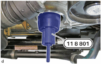
Clean the special tool 0 496 128 (11 8 801) from the set of special tools 0 496 127 (11 8 800) and coat it with fresh engine oil.
- SST
- 09200-WA080
Position the special tool 0 496 128 (11 8 801) from the set of special tools 0 496 127 (11 8 800) on the crankshaft and bolt it on.
- SST
- 09200-WA080
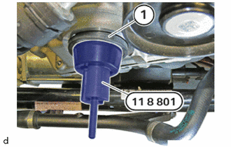
Replace front crankshaft oil seal (1).
Carefully slide the front crankshaft oil seal (1) straight in a rotational movement onto the special tool 0 496 128 (11 8 801) from the set of special tools 0 496 127 (11 8 800) until the front crankshaft oil seal is positioned flush against the cylinder block sub-assembly.
- SST
- 09200-WA080
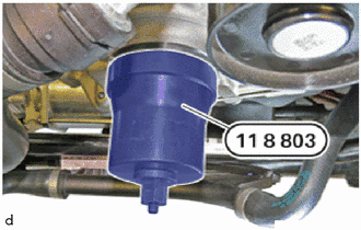
Position the special tool 0 496 130 (11 8 803) from the set of special tools 0 496 127 (11 8 800) and bolt on hand-tight with the nut.
- SST
- 09200-WA080
Ensure that the front crankshaft oil seal moves in evenly.
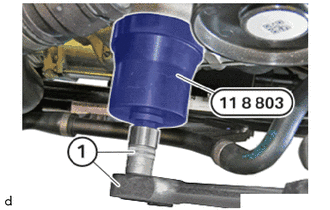
Bolt in the special tool (sleeve) 0 496 130 (11 8 803) from the set of special tools 0 496 127 (11 8 800) with the tool (1) until the special tool (sleeve)0 496 130 (11 8 803) is flush with the cylinder block sub-assembly.
- SST
- 09200-WA080
13470
2.INSTALL CRANKSHAFT PULLEY ASSEMBLY
- HINT:
-
When removing and installing or replacing the crankshaft pulley assembly, the front crankshaft oil seal must be replaced.
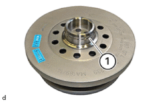
Clean the sealing surface (1) from oil and contamination.
Check if the special tool 0 496 595 (11 6 130) is installed and positioned correctly.
- SST
- 09700-WA040
Special tool 0 496 595 (11 6 130) not installed.
- SST
- 09700-WA040
Install special tool 0 496 595 (11 6 130).
- SST
- 09700-WA040
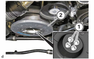
Install crankshaft pulley assembly (2) from the top and position correctly.
Tighten the E12 bolts (1).
- Torque:
- 40 N*m (408 kgf*cm, 30 ft.*lbf)
Using SST, tighten the bolts an additional 120°.
- SST
- 09900-WA010
- HINT:
-
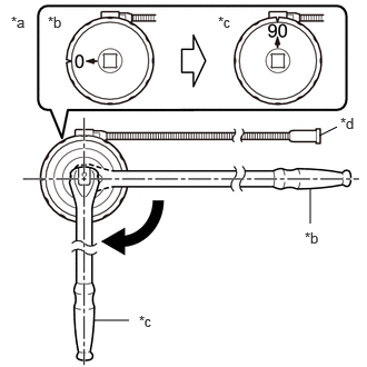 2.99,1.271 3.156,1.188 false 2.906,2.094 2.906,1.76 false 0.875,3 1.208,3 false 0.104,0.125 0.417,0.281 0.313,0.156 10 false *a 0.448,0.125 0.76,0.281 0.313,0.156 10 false *b 2.042,0.125 2.354,0.281 0.313,0.156 10 false *c 3.188,1.073 3.427,1.271 0.24,0.198 10 false *d 2.854,2.146 3.167,2.302 0.313,0.156 10 false *b 1.302,2.927 1.615,3.083 0.313,0.156 10 false *c
*a Example *b Before Tightening *c After Tightening *d Magnetic Portion
- ·
The magnetic portion is used to secure the gauge to the vehicle.
·After first adjusting the needle of the gauge to 0°, tighten to the specified angle.
·Perform the work procedure carefully so that the gauge, etc. does not become tilted.
Remove special tool 0 496 595 (11 6 130).
- SST
- 09700-WA040
28100
3.INSTALL STARTER ASSEMBLY
51219
4.INSTALL FRONT SUSPENSION MEMBER LOWER PROTECTOR
5.INSTALL FAN AND GENERATOR V BELT
16711
6.INSTALL FAN SHROUD
17880
7.INSTALL AIR CLEANER HOSE ASSEMBLY
17700
8.INSTALL AIR CLEANER ASSEMBLY
12601B
9.INSTALL NO. 1 ENGINE COVER SUB-ASSEMBLY
10.CONNECT CABLE TO NEGATIVE BATTERY TERMINAL