AXLE AND DIFFERENTIAL REAR AXLE CARRIER INSTALLATION
CAUTION / NOTICE / HINT
- HINT:
- ·
Use the same procedure for the RH side and LH side.
·The following procedure is for the LH side.
PROCEDURE

 42305
1.INSTALL REAR AXLE CARRIER SUB-ASSEMBLY
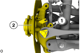
Insert and install the rear axle carrier sub-assembly (2).
Replace the bolt (1).
Tighten down bolt (1).
- Torque:
- 100 N*m (1020 kgf*cm, 74 ft.*lbf)
Using SST, tighten the bolt (1) an additional 90°.
- SST
- 09900-WA010
- HINT:
-
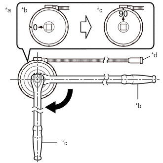 2.99,1.271 3.156,1.188 false 2.906,2.094 2.906,1.76 false 0.875,3 1.208,3 false 0.104,0.125 0.417,0.281 0.313,0.156 10 false *a 0.448,0.125 0.76,0.281 0.313,0.156 10 false *b 2.042,0.125 2.354,0.281 0.313,0.156 10 false *c 3.188,1.073 3.427,1.271 0.24,0.198 10 false *d 2.854,2.146 3.167,2.302 0.313,0.156 10 false *b 1.302,2.927 1.615,3.083 0.313,0.156 10 false *c
*a Example *b Before Tightening *c After Tightening *d Magnetic Portion
- ·
The magnetic portion is used to secure the gauge to the vehicle.
·After first adjusting the needle of the gauge to 0°, tighten to the specified angle.
·Perform the work procedure carefully so that the gauge, etc. does not become tilted.
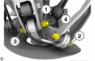
Replace the nut (1) and 18 mm nut (2).
Replace the E20 bolt (3) and 16 mm bolt (4).
Insert E20 bolt (3) and 16 mm bolt (4).
Tighten nut (1).
- Torque:
- 165 N*m (1683 kgf*cm, 122 ft.*lbf)
Using SST, tighten the nut (1) an additional 90°.
- SST
- 09900-WA010
- HINT:
-
2.99,1.271 3.156,1.188 false 2.906,2.094 2.906,1.76 false 0.875,3 1.208,3 false 0.104,0.125 0.417,0.281 0.313,0.156 10 false *a 0.448,0.125 0.76,0.281 0.313,0.156 10 false *b 2.042,0.125 2.354,0.281 0.313,0.156 10 false *c 3.188,1.073 3.427,1.271 0.24,0.198 10 false *d 2.854,2.146 3.167,2.302 0.313,0.156 10 false *b 1.302,2.927 1.615,3.083 0.313,0.156 10 false *c
*a Example *b Before Tightening *c After Tightening *d Magnetic Portion
- ·
The magnetic portion is used to secure the gauge to the vehicle.
·After first adjusting the needle of the gauge to 0°, tighten to the specified angle.
·Perform the work procedure carefully so that the gauge, etc. does not become tilted.
Tighten 18 mm nut (2).
- Torque:
- 100 N*m (1020 kgf*cm, 74 ft.*lbf)
Using SST, tighten the 18 mm nut (2) an additional 90°.
- SST
- 09900-WA010
- HINT:
-
2.99,1.271 3.156,1.188 false 2.906,2.094 2.906,1.76 false 0.875,3 1.208,3 false 0.104,0.125 0.417,0.281 0.313,0.156 10 false *a 0.448,0.125 0.76,0.281 0.313,0.156 10 false *b 2.042,0.125 2.354,0.281 0.313,0.156 10 false *c 3.188,1.073 3.427,1.271 0.24,0.198 10 false *d 2.854,2.146 3.167,2.302 0.313,0.156 10 false *b 1.302,2.927 1.615,3.083 0.313,0.156 10 false *c
*a Example *b Before Tightening *c After Tightening *d Magnetic Portion
- ·
The magnetic portion is used to secure the gauge to the vehicle.
·After first adjusting the needle of the gauge to 0°, tighten to the specified angle.
·Perform the work procedure carefully so that the gauge, etc. does not become tilted.
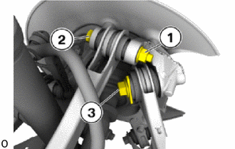
Replace the 18 mm nut (1).
Replace the 18 mm bolt (2) and bolt (3).
Insert the 18 mm bolt (2).
Tighten 18 mm nut (1).
- Torque:
- 100 N*m (1020 kgf*cm, 74 ft.*lbf)
Using SST, tighten the 18 mm nut (1) an additional 90°.
- SST
- 09900-WA010
- HINT:
-
2.99,1.271 3.156,1.188 false 2.906,2.094 2.906,1.76 false 0.875,3 1.208,3 false 0.104,0.125 0.417,0.281 0.313,0.156 10 false *a 0.448,0.125 0.76,0.281 0.313,0.156 10 false *b 2.042,0.125 2.354,0.281 0.313,0.156 10 false *c 3.188,1.073 3.427,1.271 0.24,0.198 10 false *d 2.854,2.146 3.167,2.302 0.313,0.156 10 false *b 1.302,2.927 1.615,3.083 0.313,0.156 10 false *c
*a Example *b Before Tightening *c After Tightening *d Magnetic Portion
- ·
The magnetic portion is used to secure the gauge to the vehicle.
·After first adjusting the needle of the gauge to 0°, tighten to the specified angle.
·Perform the work procedure carefully so that the gauge, etc. does not become tilted.
Tighten down bolt (3).
- Torque:
- 165 N*m (1683 kgf*cm, 122 ft.*lbf)
Using SST, tighten the bolt (3) an additional 90°.
- SST
- 09900-WA010
- HINT:
-
2.99,1.271 3.156,1.188 false 2.906,2.094 2.906,1.76 false 0.875,3 1.208,3 false 0.104,0.125 0.417,0.281 0.313,0.156 10 false *a 0.448,0.125 0.76,0.281 0.313,0.156 10 false *b 2.042,0.125 2.354,0.281 0.313,0.156 10 false *c 3.188,1.073 3.427,1.271 0.24,0.198 10 false *d 2.854,2.146 3.167,2.302 0.313,0.156 10 false *b 1.302,2.927 1.615,3.083 0.313,0.156 10 false *c
*a Example *b Before Tightening *c After Tightening *d Magnetic Portion
- ·
The magnetic portion is used to secure the gauge to the vehicle.
·After first adjusting the needle of the gauge to 0°, tighten to the specified angle.
·Perform the work procedure carefully so that the gauge, etc. does not become tilted.
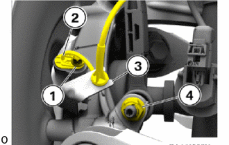
Install the rear stabilizer link assembly on the rear axle carrier sub-assembly.
Replace 16 mm nut (4).
Tighten the 16 mm nut (4).
- Torque:
- 56 N*m (571 kgf*cm, 41 ft.*lbf)
- HINT:
-
If necessary, counter support the T30 "TORX" socket wrench.
Install skid control sensor wire (2).
Replace the E11 bolt (1).
Tighten down E11 bolt (1).
- Torque:
- 11.8 N*m (120 kgf*cm, 9 ft.*lbf)
Attach the cable in the holder (3).
2.INSTALL REAR COIL SPRING
3.INSTALL REAR DISC BRAKE DUST COVER
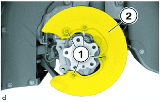
Install the rear disc brake dust cover (2).
Replace bolts (1).
Tighten the bolts (1).
- Torque:
- 8.0 N*m (82 kgf*cm, 71 in.*lbf)
4.INSTALL REAR BRAKE DISC
42340B
5.INSTALL REAR DRIVE SHAFT ASSEMBLY
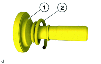
Replace bolt (1) and compression spring (2).
Position the rear drive shaft assembly on the rear axle hub and bearing assembly from the center of the vehicle.
Hand-tighten the bolt (1) with the compression spring (2).
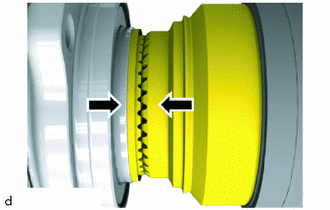
Check whether front gearing is locked tooth in tooth by reciprocally rotating the rear axle hub and bearing assembly and the rear drive shaft assembly.
If positive locking is ensured: Press brake pedal.
Using a 17 mm straight hexagon wrench, tighten the bolt (1).
- Torque:
- 210 N*m (2141 kgf*cm, 155 ft.*lbf)
Tighten the bolt (1) an additional 90°.
- SST
- 09900-WA010
- HINT:
-
2.99,1.271 3.156,1.188 false 2.906,2.094 2.906,1.76 false 0.875,3 1.208,3 false 0.104,0.125 0.417,0.281 0.313,0.156 10 false *a 0.448,0.125 0.76,0.281 0.313,0.156 10 false *b 2.042,0.125 2.354,0.281 0.313,0.156 10 false *c 3.188,1.073 3.427,1.271 0.24,0.198 10 false *d 2.854,2.146 3.167,2.302 0.313,0.156 10 false *b 1.302,2.927 1.615,3.083 0.313,0.156 10 false *c
*a Example *b Before Tightening *c After Tightening *d Magnetic Portion
- ·
The magnetic portion is used to secure the gauge to the vehicle.
·After first adjusting the needle of the gauge to 0°, tighten to the specified angle.
·Perform the work procedure carefully so that the gauge, etc. does not become tilted.
Install the sealing cap.
6.INSTALL REAR WHEEL
7.INSPECT AND ADJUST FRONT WHEEL ALIGNMENT
8.INSPECT AND ADJUST REAR WHEEL ALIGNMENT