DRIVE SHAFT / PROPELLER SHAFT FLEXIBLE COUPLING REMOVAL
PROCEDURE

 50819
1.REMOVE FRONT FLOOR COVER
58166A
2.REMOVE FRONT FLOOR COVER LH
58165C
3.REMOVE FRONT FLOOR COVER RH
- HINT:
-
Use the same procedure as for the LH side.
4.REMOVE EXHAUST PIPE ASSEMBLY (for B48)
5.REMOVE EXHAUST PIPE ASSEMBLY (for B58)
58151
6.REMOVE FRONT NO. 1 FLOOR HEAT INSULATOR
57255
7.REMOVE REAR ENGINE MOUNTING MEMBER
37100
8.SEPARATE PROPELLER SHAFT ASSEMBLY WITH CENTER BEARING (for Front Side)
- NOTICE:
- ·
Damage to propeller shaft assembly with center bearing during removal.
Non-observance of the removal guidelines for the propeller shaft assembly with center bearing on the rear axle differential may cause severe damage.
-Do not disassemble the three-hole flange, flexible coupling and propeller shaft assembly with center bearing. The three-hole flange to the rear axle differential is balanced with the flexible coupling and propeller shaft assembly with center bearing.
-Loosen the recessed nut against the direction of travel in clockwise direction. The propeller shaft assembly with center bearing must be loosened on the recessed nut only and exclusively in the direction of rotation otherwise the anti-twist lock of the bi-hexagonal flange nut is damaged.
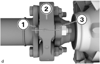
Mark the installation position of the 18 mm bolts connection (2) of the flexible coupling (1) and the three-hole flange (3).
The mark makes it possible for the propeller shaft assembly with center bearing to be installed again in the same position. This should prevent a humming noise from the drive train during driving.
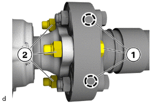
Release 18 mm bolts (1) and counter the 18 mm nuts (2).
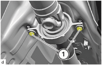
Remove the bolts (1) on the center No. 1 support bearing assembly and hold down the propeller shaft assembly with center bearing.
- NOTICE:
-
Major deflection angles of the propeller shaft assembly with center bearing may damage the propeller shaft assembly with center bearing and/or the joints.
Tie up propeller shaft assembly with center bearing to underbody.
37100
9.SEPARATE PROPELLER SHAFT ASSEMBLY WITH CENTER BEARING (for Rear Side)
- NOTICE:
- ·
Damage to propeller shaft assembly with center bearing during removal.
Non-observance of the removal guidelines for the propeller shaft assembly with center bearing on the rear axle differential may cause severe damage.
-Do not disassemble the three-hole flange, flexible coupling and propeller shaft assembly with center bearing. The three-hole flange to the rear axle differential is balanced with the flexible coupling and propeller shaft assembly with center bearing.
-Loosen the recessed nut against the direction of travel in clockwise direction. The propeller shaft assembly with center bearing must be loosened on the recessed nut only and exclusively in the direction of rotation otherwise the anti-twist lock of the bi-hexagonal flange nut is damaged.
- HINT:
-
To protect universal joints, tie back propeller shaft assembly with center bearing in area of center bearing.
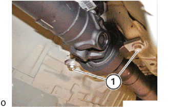
Remove the bolts (1) on the center No. 1 support bearing assembly and hold down the propeller shaft assembly with center bearing.
- NOTICE:
-
Major deflection angles of the propeller shaft assembly with center bearing may damage the propeller shaft assembly with center bearing and/or the joints.
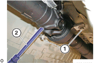
Secure the propeller shaft assembly with center bearing against twisting at the central universal joint using a suitable tool (2).
- HINT:
-
Remove bolts completely (1) only after opening the bolts on the 3-hole flange.
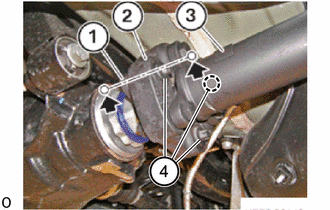
Mark the installation position of the three-hole flange (1), the flexible disc (2) and the propeller shaft (3) on the same level (arrows).
- HINT:
-
The identification allows the three-hole flange and the propeller shaft to be installed at the same position. This guarantees that the three-hole punch for the rear axle differential will once again be balanced with the propeller shaft after installation.
Remove the E16 bolts (4).
Detach the propeller shaft assembly with center bearing (3) at the three-hole flange (1) and at the center mount.
10.REMOVE FLEXIBLE COUPLING (for Front Side)
- HINT:
-
To protect universal joints, tie back propeller shaft assembly with center bearing in area of center mount.
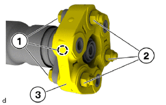
Release the 18 mm bolts (1), if necessary counter support at the 18 mm nuts (2).
Remove the flexible coupling (3) from the propeller shaft assembly with center bearing.
11.REMOVE FLEXIBLE COUPLING (for Rear Side)
- HINT:
-
To protect universal joints, tie back propeller shaft assembly with center bearing in area of center mount.
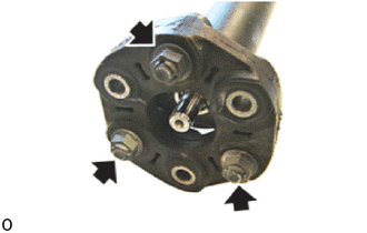
Release 18 mm bolts and counter the 18 mm nuts and remove flexible disc from the propeller shaft assembly with center bearing.