8HP51 AUTOMATIC TRANSMISSION / TRANSAXLE AUTOMATIC TRANSMISSION ASSEMBLY REMOVAL
PROCEDURE

 1.DISCONNECT CABLE FROM NEGATIVE BATTERY TERMINAL (for B48)
Click hereGeneral>MAINTENANCE>B48 BATTERY>REMOVAL
2.DISCONNECT CABLE FROM NEGATIVE BATTERY TERMINAL (for B58)
Click hereGeneral>MAINTENANCE>B58 BATTERY>REMOVAL
53440A
3.REMOVE AND INSTALL HOOD SUPPORT ASSEMBLY (for B58)
12601B
4.REMOVE NO. 1 ENGINE COVER SUB-ASSEMBLY (for B58)
53826A
5.REMOVE FRONT FENDER UPPER PROTECTOR LH (for B58)
53825A
6.REMOVE FRONT FENDER UPPER PROTECTOR RH (for B58)
- HINT:
-
Use the same procedure as for the LH side.
7.INSTALL ENGINE HANGER (for B58)
8.INSTALL ENGINE SUPPORT BRIDGE (for B58)
for Type A:
Click hereSuspension>FRONT SUSPENSION>FRONT SUSPENSION MEMBER>REMOVAL
for Type B:
Click hereSuspension>FRONT SUSPENSION>FRONT SUSPENSION MEMBER>REMOVAL
51219
9.REMOVE FRONT SUSPENSION MEMBER LOWER PROTECTOR
28100
10.REMOVE STARTER ASSEMBLY (for B48)
28100
11.REMOVE STARTER ASSEMBLY (for B58)
58166A
12.REMOVE FRONT FLOOR COVER LH
58165C
13.REMOVE FRONT FLOOR COVER RH
- HINT:
-
Use the same procedure as for the LH side.
14.REMOVE EXHAUST PIPE ASSEMBLY (for B48)
15.REMOVE EXHAUST PIPE ASSEMBLY (for B58)
58151
16.REMOVE FRONT NO. 1 FLOOR HEAT INSULATOR
58152C
17.REMOVE FLOOR HEAT INSULATOR
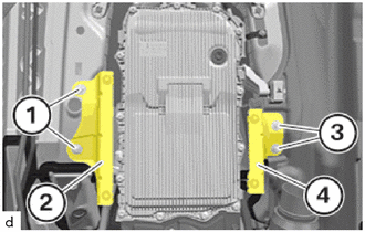
Loosen nuts (1).
Remove the No. 1 floor heat Insulator (2).
Loosen nuts (3).
Remove the No. 2 floor heat Insulator (4).
57255
18.REMOVE REAR ENGINE MOUNTING MEMBER
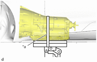
| *a | Lashing Belt |
Support the automatic transmission assembly with a transmission jack.
- CAUTION:
-
Secure the automatic transmission assembly to the transmission jack using a lashing belt, etc. to prevent it from falling.
- NOTICE:
- ·
Place attachments on the transmission jack saddle.
·Make sure that the attachments and the transmission oil sump are centered on the transmission jack.
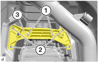
Loosen the bolts (2).
Loosen nuts (1).
Remove the rear engine mounting member (3).
19.SEPARATE PROPELLER SHAFT ASSEMBLY
- NOTICE:
- ·
Damage to propeller shaft assembly during removal.
Non-observance of the removal guidelines for the propeller shaft assembly on the rear differential carrier assembly may cause severe damage.
-Do not disassemble the three-hole flange, flexible disc and propeller shaft assembly. The three-hole flange to the rear differential carrier assembly is balanced with the flexible disc and propeller shaft assembly.
-Loosen the recessed nut against the direction of travel in clockwise direction. The propeller shaft assembly must be loosened on the recessed nut only and exclusively in the direction of rotation otherwise the anti-twist lock of the bi-hexagonal flange nut is damaged.
-In the event of a damaged anti-twist lock on the bi-hexagonal flange nut: Replace the rear differential carrier assembly.
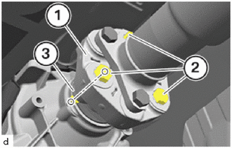
Mark the installation position of the bolt connections (2) of the flexible coupling (1) and the output flange (3).
- HINT:
- ·
The mark makes it possible for the propeller shaft assembly to be installed again in the same position.
·This should prevent a humming noise from the drive train during driving.
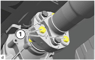
Loosen 18 mm bolts (1).
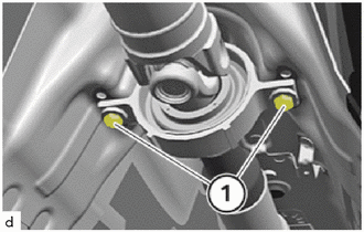
Unscrew the bolts (1) on the center bearing and hold down the propeller shaft assembly.
- NOTICE:
-
Major deflection angles of the propeller shaft assembly may damage the propeller shaft assembly and/or the joints.
Tie up propeller shaft assembly to underbody.
17119
20.REMOVE NO. 2 MANIFOLD STAY (for B48)
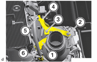
Detach the cable of the front oxygen sensor (4) from the No. 2 manifold stay (1).
Detach the cable (6) from the No. 2 manifold stay (1).
Unscrew the bolts (5) and (3) and the nut (2).
Remove the No. 2 manifold stay (1).
17119
21.REMOVE NO. 2 MANIFOLD STAY (for B58)
- CAUTION:
- ·
Hot surfaces.
Risk of burning!
-Perform all work only on components that have cooled down.
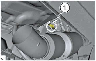
Loosen the nuts (1).
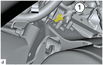
Disengage tab (1) to the top.
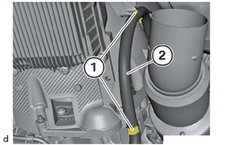
Detach starter cable (2) from the clamps (1).
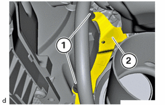
Loosen the bolts (1).
Thread out and remove the No. 2 manifold stay (2).
82284A
22.DISCONNECT NO. 2 EARTH WIRE
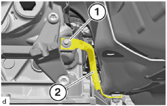
Unfasten the nut (1).
Detach the No. 2 earth wire (2) from the automatic transmission assembly.
23.DISCONNECT OIL COOLER TUBE
- CAUTION:
- ·
Materials harmful to health.
Contact with fluids harmful to health!
-Note and follow safety information on containers.
-Conduct all work in appropriate personal protective equipment only.
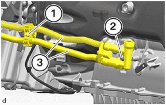
Release the T25 screw (1) and bolt (2).
Disconnect the oil cooler tubes (3) at the automatic transmission assembly.
35128
24.REMOVE TRANSMISSION HOUSING UNDER COVER (for B48)
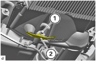
Loosen the E10 bolt (1).
Remove holder (2).
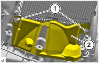
Loosen the expanding rivet (1).
Remove the transmission housing under cover (2).
11401T
25.REMOVE CYLINDER BLOCK COVER (for B48)
26.REMOVE DRIVE PLATE AND TORQUE CONVERTER ASSEMBLY SETTING BOLT
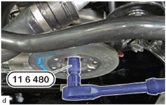
Turn the engine on the crankshaft pulley assembly with the special tool 0 493 380 (11 6 480) in the direction of rotation until a drive plate and torque converter assembly setting bolt (1) becomes visible in the recess.
- SST
- 09200-WA190
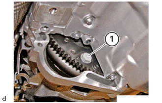
Release the drive plate and torque converter assembly setting bolt (1) of the torque converter.
- HINT:
-
Repeat this procedure for all bolts.
27.INSTALL SPECIAL TOOL TO FIX THE TORQUE CONVERTER
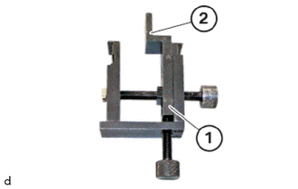
Prepare special tool 0 494 478 (24 4 161) (1) with the special tool 0 496 061 (24 4 166) (2) as shown.
- SST
- 09300-WA030
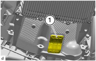
Remove the transmission housing cover (1).
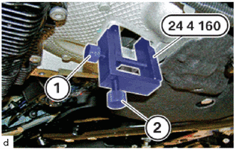
Insert special tool 0 494 451 (24 4 160) into the recess of the transmission housing and apply slight tension using the screw (1).
- SST
- 09300-WA030
Screw the screw (2) in to the stop.
Tighten down screw (1).
28.REMOVE WIRE HARNESS
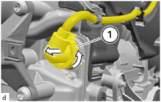
Unlock connector (1) by turning and pull off.
- NOTICE:
-
Do not touch pins.
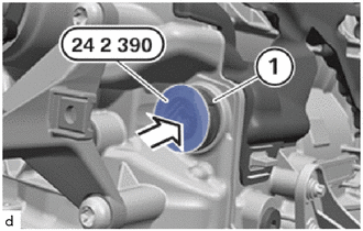
Insert special tool 0 494 213 (24 2 390) in sealing sleeve (1).
- SST
- 09300-WA100
35000
29.REMOVE AUTOMATIC TRANSMISSION ASSEMBLY
- CAUTION:
- ·
Materials harmful to health.
Contact with fluids harmful to health!
-Note and follow safety information on containers.
-Conduct all work in appropriate personal protective equipment only.
- NOTICE:
- ·
Damage to the engine block.
Damaged and corroded bolts will lead to major damage in the engine block and the automatic transmission assembly.
-It is imperative that protruding threads of the automatic transmission assembly bolts are checked for corrosion and damage prior to removal.
-It is imperative that all rust is removed from corroded threads and that they are cleaned prior to removal.
-Replace rusted and damaged bolts.
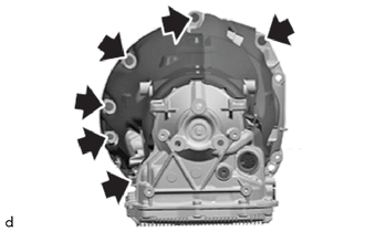
for B48:
Unscrew the E10 bolts and E14 bolts.
Remove the automatic transmission assembly.
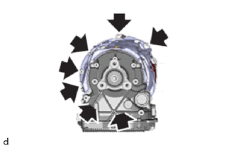
for B58:
Unscrew the E10 bolts and E14 bolts.
Remove the automatic transmission assembly.
30.REMOVE TORQUE CONVERTER
- CAUTION:
- ·
Materials harmful to health.
Contact with fluids harmful to health!
-Note and follow safety information on containers.
-Conduct all work in appropriate personal protective equipment only.
- HINT:
-
Collect and dispose of emerging fluids. Observe country-specific waste disposal regulations.
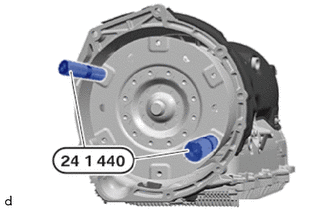
Screw the special tool 0 496 717 (24 1 440) into the torque converter.
- SST
- 09300-WA040
Remove torque converter and set down vertically.
- HINT:
-
Drain, catch and dispose of the automatic transmission fluid.
12371A
31.REMOVE REAR ENGINE MOUNTING INSULATOR
- HINT:
-
Perform this procedure only when replacement of the rear engine mounting insulator is necessary.
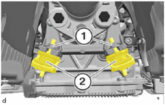
Loosen nuts (1).
Remove the rear engine mounting insulator (2).
12303
32.REMOVE REAR ENGINE MOUNTING BRACKET SUB-ASSEMBLY
- HINT:
-
Perform this procedure only when replacement of the rear engine mounting bracket sub-assembly is necessary.
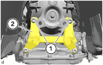
Loosen the T55 bolts (1).
Remove the rear engine mounting bracket sub-assembly (2).