DRIVE SHAFT / PROPELLER SHAFT FLEXIBLE COUPLING INSTALLATION
CAUTION / NOTICE / HINT
PROCEDURE

 1.INSTALL FLEXIBLE COUPLING (for Front Side)
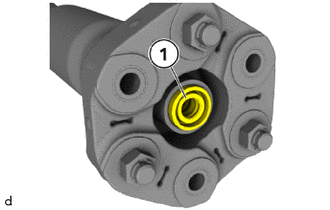
Check center No. 1 support bearing assembly (1) for damage; replace if necessary.
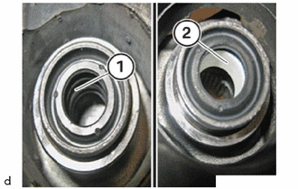
Apply a thin coat of Lubricant Olistamoly 2 LN 584 LO to the soft centering (1), if necessary.
- NOTICE:
-
Do not grease the hard centering (2).
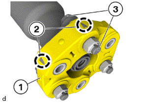
Replace 18 mm bolts and 18 mm self-locking nuts.
During the installation, make sure that the arrows (2) on the circumference of the flexible coupling point to the flange arms (3).
Mount flexible coupling (1) on the propeller shaft assembly with center bearing and tighten the 18 mm bolts.
- Torque:
- 55 N*m (561 kgf*cm, 41 ft.*lbf)
Tighten the 18 mm bolts an additional 90° and counter support them at the 18 mm nuts.
- SST
- 09900-WA010
- NOTICE:
-
Jointing torque and angle of rotation must be observed without fail.
- HINT:
- ·
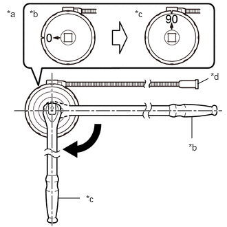 2.99,1.271 3.156,1.188 false 2.906,2.094 2.906,1.76 false 0.875,3 1.208,3 false 0.104,0.125 0.417,0.281 0.313,0.156 10 false *a 0.448,0.125 0.76,0.281 0.313,0.156 10 false *b 2.042,0.125 2.354,0.281 0.313,0.156 10 false *c 3.188,1.073 3.427,1.271 0.24,0.198 10 false *d 2.854,2.146 3.167,2.302 0.313,0.156 10 false *b 1.302,2.927 1.615,3.083 0.313,0.156 10 false *c
*a Example *b Before Tightening *c After Tightening *d Magnetic Portion
·The magnetic portion is used to secure the gauge to the vehicle.
·After first adjusting the needle of the gauge to 0°, tighten to the specified angle.
·Perform the work procedure carefully so that the gauge, etc. does not become tilted.
2.INSTALL FLEXIBLE COUPLING (for Rear Side)
Replace 18 mm bolts and 18 mm self-locking nuts.
Mount the flexible disc on the propeller shaft assembly with center bearing and tighten the 18 mm bolts.
- Torque:
- 55 N*m (561 kgf*cm, 41 ft.*lbf)
Tighten the 18 mm bolts an additional 90° and counter support them at the 18 mm nuts.
- SST
- 09900-WA010
- NOTICE:
-
Jointing torque and angle of rotation must be observed without fail.
- HINT:
- ·
2.99,1.271 3.156,1.188 false 2.906,2.094 2.906,1.76 false 0.875,3 1.208,3 false 0.104,0.125 0.417,0.281 0.313,0.156 10 false *a 0.448,0.125 0.76,0.281 0.313,0.156 10 false *b 2.042,0.125 2.354,0.281 0.313,0.156 10 false *c 3.188,1.073 3.427,1.271 0.24,0.198 10 false *d 2.854,2.146 3.167,2.302 0.313,0.156 10 false *b 1.302,2.927 1.615,3.083 0.313,0.156 10 false *c
*a Example *b Before Tightening *c After Tightening *d Magnetic Portion
·The magnetic portion is used to secure the gauge to the vehicle.
·After first adjusting the needle of the gauge to 0°, tighten to the specified angle.
·Perform the work procedure carefully so that the gauge, etc. does not become tilted.
37100
3.INSTALL PROPELLER SHAFT ASSEMBLY WITH CENTER BEARING (for Front Side)
Check center No. 1 support bearing assembly for damage, replace if necessary.
Apply a thin coat of Lubricant Olistamoly 2 LN 584 LO to the soft centering (1), if necessary.
Do not grease the hard centering (2).
Replace the 18 mm bolts and 18 mm self-locking nuts.
Assemble the 18 mm bolts connections of the flexible coupling and the three-hole flange according to the self-affixed identification.
This should prevent a humming noise from thedrive train during driving.
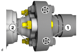
Hand-tighten 18 mm bolts (1) and 18 mm nuts (2), but do not tighten fully.
center mount with TOP marking:
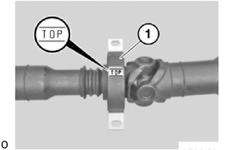
The center mount (1) must be installed with the TOP marking at the top in the gearbox tunnel.
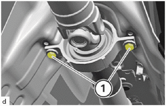
Position center mount.
Hand-tighten bolts (1), but do not tighten fully.
Provide counter support for the 18 mm bolts of the flexible coupling on the 18 mm nut and tighten with the 18 mm bolts.
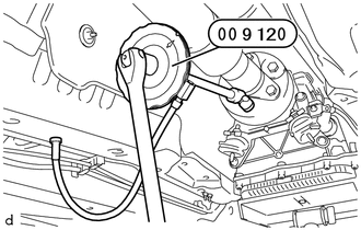
Secure the special tool 0 490 504 (00 9 120) with the special tool 0 495 108 (00 9 130) on the vehicle underbody and continue to 18 mm bolts it in according to the angle of rotation.
- SST
- 09900-WA010
- Torque:
- 55 N*m (561 kgf*cm, 41 ft.*lbf)
Tighten the 18 mm bolts an additional 90° and counter support them at the 18 mm nuts.
- NOTICE:
-
Jointing torque and angle of rotation must be observed without fail.
- HINT:
- ·
2.99,1.271 3.156,1.188 false 2.906,2.094 2.906,1.76 false 0.875,3 1.208,3 false 0.104,0.125 0.417,0.281 0.313,0.156 10 false *a 0.448,0.125 0.76,0.281 0.313,0.156 10 false *b 2.042,0.125 2.354,0.281 0.313,0.156 10 false *c 3.188,1.073 3.427,1.271 0.24,0.198 10 false *d 2.854,2.146 3.167,2.302 0.313,0.156 10 false *b 1.302,2.927 1.615,3.083 0.313,0.156 10 false *c
*a Example *b Before Tightening *c After Tightening *d Magnetic Portion
·The magnetic portion is used to secure the gauge to the vehicle.
·After first adjusting the needle of the gauge to 0°, tighten to the specified angle.
·Perform the work procedure carefully so that the gauge, etc. does not become tilted.
Tighten the bolts (1).
- Torque:
- 21.4 N*m (218 kgf*cm, 16 ft.*lbf)
37100
4.INSTALL PROPELLER SHAFT ASSEMBLY WITH CENTER BEARING (for Rear Side)
center mount with TOP marking:
The center mount (1) must be installed with the TOP marking at the top in the gearbox tunnel.
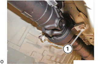
Position center mount.
Position the bolts (1).
Secure the propeller shaft against twisting at the central universal joint using a suitable tool.
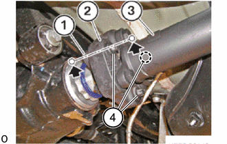
Assemble the three-hole flange (1), flexible disc (2) and propeller shaft (3) in the same position that was marked during the removal.
Replace the E16 bolts (4).
Tighten the E16 bolts (4).
- Torque:
- 55 N*m (561 kgf*cm, 41 ft.*lbf)
Tighten the E16 bolts (4) an additional 90°.
- SST
- 09900-WA010
- NOTICE:
-
Jointing torque and angle of rotation must be observed without fail.
- HINT:
- ·
2.99,1.271 3.156,1.188 false 2.906,2.094 2.906,1.76 false 0.875,3 1.208,3 false 0.104,0.125 0.417,0.281 0.313,0.156 10 false *a 0.448,0.125 0.76,0.281 0.313,0.156 10 false *b 2.042,0.125 2.354,0.281 0.313,0.156 10 false *c 3.188,1.073 3.427,1.271 0.24,0.198 10 false *d 2.854,2.146 3.167,2.302 0.313,0.156 10 false *b 1.302,2.927 1.615,3.083 0.313,0.156 10 false *c
*a Example *b Before Tightening *c After Tightening *d Magnetic Portion
·The magnetic portion is used to secure the gauge to the vehicle.
·After first adjusting the needle of the gauge to 0°, tighten to the specified angle.
·Perform the work procedure carefully so that the gauge, etc. does not become tilted.
Tighten the bolts (1).
- Torque:
- 21.4 N*m (218 kgf*cm, 16 ft.*lbf)
57255
5.INSTALL REAR ENGINE MOUNTING MEMBER
58151
6.INSTALL FRONT NO. 1 FLOOR HEAT INSULATOR
7.INSTALL EXHAUST PIPE ASSEMBLY (for B48)
8.INSTALL EXHAUST PIPE ASSEMBLY (for B58)
58166A
9.INSTALL FRONT FLOOR COVER LH
58165C
10.INSTALL FRONT FLOOR COVER RH
- HINT:
-
Use the same procedure as for the LH side.
50819
11.INSTALL FRONT FLOOR COVER