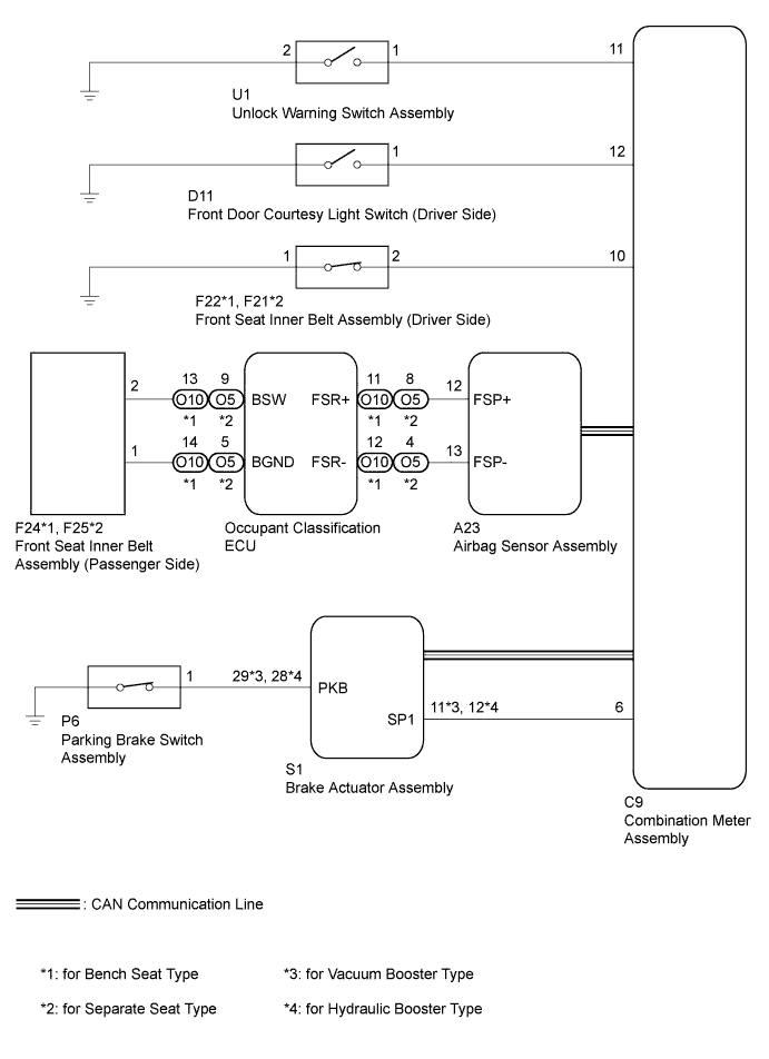
METER / GAUGE SYSTEM > Warning Buzzer does not Sound |
| 1.CHECK WARNING BUZZER |
Check that the key reminder, seat belt and parking brake warning buzzers sound.
| Result | Proceed to |
| No warning buzzers sound | A |
| Key reminder warning buzzer does not sound | B |
| Seat belt warning buzzer does not sound | C |
| Parking brake warning buzzer does not sound | C |
|
| ||||
|
| ||||
| A | ||
 | ||
| ||
| 2.INSPECT UNLOCK WARNING SWITCH ASSEMBLY |
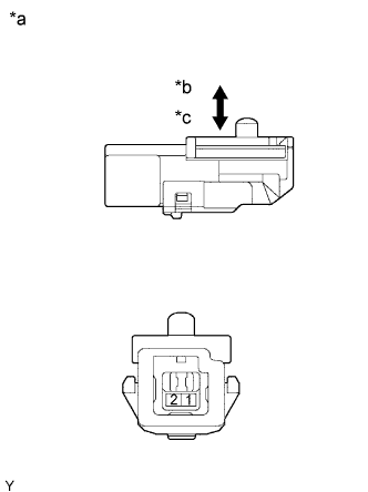 |
Remove the unlock warning switch assembly.
Measure the resistance according to the value(s) in the table below.
| Tester Connection | Switch Condition | Specified Condition |
| 1 - 2 | Not pushed | 10 kΩ or higher |
| 1 - 2 | Pushed | Below 1 Ω |
| *a | Component without harness connected (Unlock Warning Switch Assembly) |
| *b | Not Pushed |
| *c | Pushed |
Reinstall the unlock warning switch assembly.
|
| ||||
| OK | |
 |
| 3.CHECK HARNESS AND CONNECTOR (UNLOCK WARNING SWITCH ASSEMBLY - COMBINATION METER ASSEMBLY AND BODY GROUND) |
Disconnect the U1 unlock warning switch assembly connector.
Disconnect the C9 combination meter assembly connector.
Measure the resistance according to the value(s) in the table below.
| Tester Connection | Condition | Specified Condition |
| U1-1- C9-11 | Always | Below 1 Ω |
| U1-1 or C9-11 - Body ground | Always | 10 kΩ or higher |
| U1-2 - Body ground | Always | Below 1 Ω |
Reconnect the combination meter assembly connector.
Reconnect the unlock warning switch assembly connector.
|
| ||||
| OK | |
|
| 4.INSPECT FRONT DOOR COURTESY LIGHT SWITCH (DRIVER SIDE) |
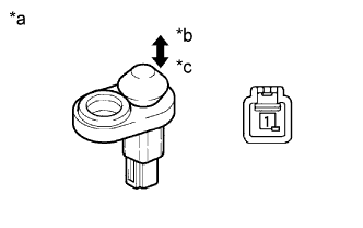 |
Remove the front door courtesy light switch (driver side).
Measure the resistance according to the value(s) in the table below.
| Tester Connection | Switch Condition | Specified Condition |
| 1 - Switch body ground | Not pushed (ON) | Below 1 Ω |
| 1 - Switch body ground | Pushed (OFF) | 10 kΩ or higher |
| *a | Component without harness connected (Front Door Courtesy Light Switch (Driver Side)) |
| *b | Not Pushed (ON) |
| *c | Pushed (OFF) |
Reinstall the front door courtesy light switch (driver side).
|
| ||||
| OK | |
|
| 5.CHECK HARNESS AND CONNECTOR (FRONT DOOR COURTESY LIGHT SWITCH (DRIVER SIDE) - COMBINATION METER ASSEMBLY) |
Disconnect the D11 front door courtesy light switch (driver side) connector.
Disconnect the C9 combination meter assembly connector.
Measure the resistance according to the value(s) in the table below.
| Tester Connection | Condition | Specified Condition |
| D11-1- C9-12 | Always | Below 1 Ω |
| D11-1 or C9-12 - Body ground | Always | 10 kΩ or higher |
Reconnect the combination meter assembly connector.
Reconnect the front door courtesy light switch (driver side) connector.
|
| ||||
| OK | ||
| ||
| ||
| 6.INSPECT COMBINATION METER ASSEMBLY (INPUT WAVEFORM) |
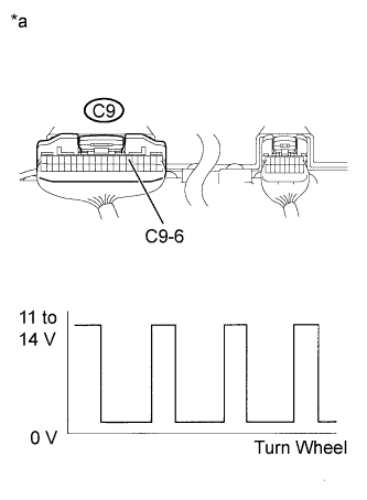 |
Move the shift lever to the neutral position.
Jack up the vehicle.
Turn the ignition switch to ON.
Check the voltage while the wheel is turning slowly.
| Tester Connection | Switch Condition | Specified Condition |
| C9-6 - Body ground | Ignition switch ON (Turn wheel slowly) | Voltage generated intermittently |
| *a | Component with harness connected (Combination Meter Assembly) |
| Result | Proceed to |
| OK (Seat belt warning buzzer does not sound (driver side)) | A |
| OK (Seat belt warning buzzer does not sound (passenger side)) | B |
| OK (Parking brake warning buzzer does not sound) | C |
| NG | D |
|
| ||||
|
| ||||
|
| ||||
| A | ||
| ||
| ||
| 7.CHECK CAN COMMUNICATION SYSTEM |
Check if a CAN communication DTC is output (Click here).
| Result | Proceed to |
| DTC is not output | A |
| DTC is output | B |
|
| ||||
| A | |
|
| 8.INSPECT PARKING BRAKE SWITCH ASSEMBLY |
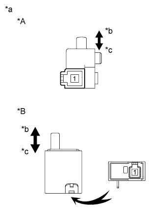 |
Remove the parking brake switch assembly.
Measure the resistance according to the value(s) in the table below.
| Tester Connection | Switch Condition | Specified Condition |
| 1 - Switch body ground | Not pushed (ON) | Below 1 Ω |
| 1 - Switch body ground | Pushed (OFF) | 10 kΩ or higher |
| *A | for Automatic Transmission |
| *B | for Manual Transmission |
| *a | Component without harness connected (Parking Brake Switch Assembly) |
| *b | Not Pushed (ON) |
| *c | Pushed (OFF) |
Reinstall the parking brake switch assembly.
|
| ||||
| OK | |
|
| 9.CHECK HARNESS AND CONNECTOR (PARKING BRAKE SWITCH ASSEMBLY - BRAKE ACTUATOR ASSEMBLY) |
Disconnect the P6 parking brake switch assembly connector.
Disconnect the S1 brake actuator assembly connector.
Measure the resistance according to the value(s) in the table below.
| Tester Connection | Condition | Specified Condition |
| P6-1 - S1-29 (PKB)*1 | Always | Below 1 Ω |
| P6-1 or S1-29 (PKB)*1 - Body ground | Always | 10 kΩ or higher |
| P6-1 - S1-28 (PKB)*2 | Always | Below 1 Ω |
| P6-1 or S1-28 (PKB)*2 - Body ground | Always | 10 kΩ or higher |
Reconnect the brake actuator assembly connector.
Reconnect the parking brake switch assembly connector.
|
| ||||
| OK | |
|
| 10.REPLACE BRAKE ACTUATOR ASSEMBLY |
Replace the brake actuator assembly with a new or a known good one (Click here).
|
| ||||
| OK | ||
| ||
| ||

