
TIMING CHAIN > INSTALLATION |
| 1. INSTALL NO.2 CHAIN SUB-ASSEMBLY |
|
Install the chain with its mark links aligned with the timing marks on the crankshaft timing sprocket and balanceshaft timing sprocket.
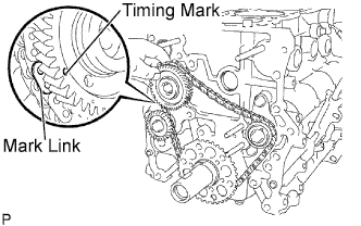 |
Bring the other mark link of the crankshaft timing sprocket behind the large timing mark of the balanceshaft drive gear.
Insert the balanceshaft drive gear shaft through the balanceshaft drive gear so that it fits into the thrust plate hole.
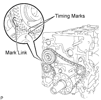 |
Align the small timing mark of the balanceshaft drive gear with the timing mark of the balanceshaft timing gear.
Install the bolt onto the balanceshaft drive gear and tighten it.
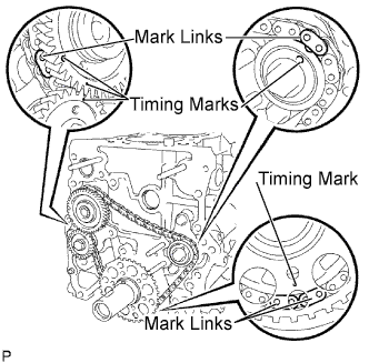 |
Check that each timing mark is aligned with the corresponding mark link.
| 2. INSTALL NO. 2 CHAIN TENSIONER ASSEMBLY |
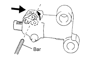 |
Install the chain tensioner with the nut.
| 3. INSTALL NO. 3 CHAIN VIBRATION DAMPER |
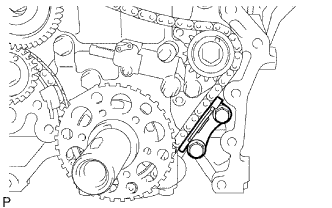 |
Install the No. 3 chain vibration damper with the 2 bolts.
| 4. INSTALL CHAIN VIBRATION DAMPER NO.2 |
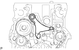 |
Install the chain vibration damper with the bolt.
Remove the pin from the chain tensioner and release the plunger.
| 5. INSTALL CRANKSHAFT TIMING GEAR OR SPROCKET |
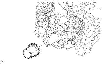 |
Install the timing sprocket as shown in the illustration.
| 6. INSTALL NO. 1 CHAIN VIBRATION DAMPER |
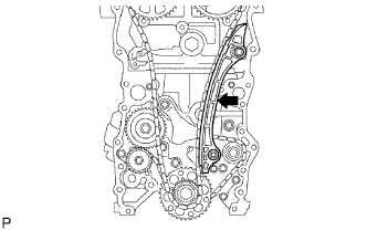 |
Install the vibration damper with the bolt and nut.
| 7. INSTALL CHAIN SUB-ASSEMBLY |
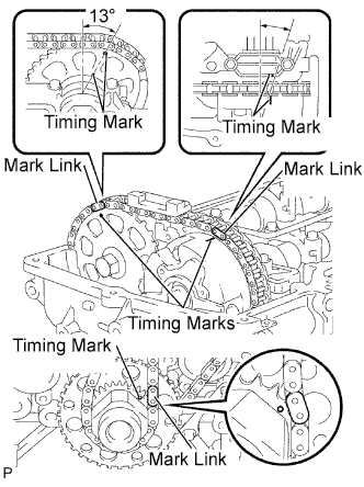 |
As shown in the illustration, install the chain onto the sprocket and gear with the painted marks aligned with the timing marks on the sprocket and gear.
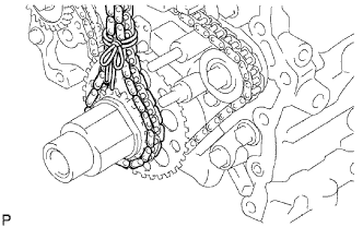 |
Use a rope to tie the chain of the crankshaft timing sprocket. Tie the rope near the sprocket.
| 8. INSTALL CHAIN TENSIONER SLIPPER |
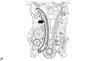 |
Install the tensioner slipper with the bolt.
| 9. INSTALL NO. 1 CHAIN TENSIONER ASSEMBLY |
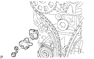 |
Install a new gasket and the chain tensioner with the bolt and nut.
| 10. INSTALL TIMING CHAIN GUIDE |
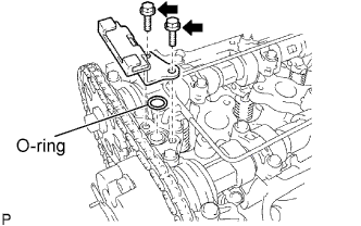 |
Install a new O-ring and the chain guide with the 2 bolts.
| 11. INSTALL TIMING CHAIN COVER |
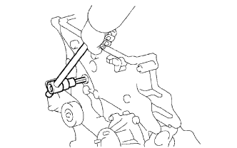 |
Apply adhesive to the head straight screw plug.
Using a 10 mm socket hexagon wrench, install the head straight screw plug.
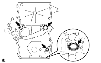 |
Install 4 new O-rings onto the oil pump as shown in the illustration.
Apply continuous beads of seal packing to the places shown in the illustration.
| Position | Specified Condition |
| A - A' | 2.5 to 3.0 mm (0.098 to 0.118 in.) |
| B - B', C - C' | 4.0 to 4.5 mm (0.157 to 0.177 in.) |
| D - D' | 2.5 to 3.0 mm (0.098 to 0.118 in.) |
| E | 2.5 to 3.5 mm (0.098 to 0.138 in.) |

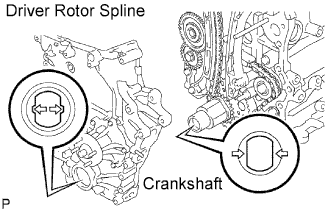 |
Align the oil pump's drive rotor spline and the crankshaft as shown in the illustration. Install the spline and chain cover onto the crankshaft.
Loosely install the oil pump with the 19 bolts and 2 nuts, but do not tighten the bolts and nuts yet.
 |
Provisionally install the oil pump with the 19 bolts and 2 nuts.
Fully tighten the bolts and nuts, except bolts A, in the following order: Area 1, Area 3 and then Area 2.
Fully tighten the bolts A in the following order: Area 2 and then Area 3.
Fully tighten the bolts E in Area 4.
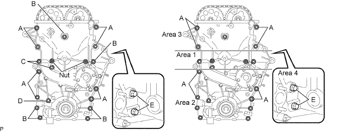
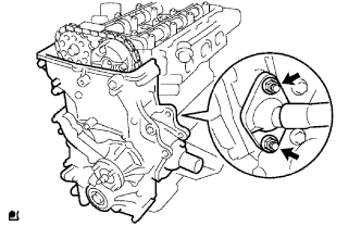 |
Install a new gasket, then install the water by-pass pipe No. 1 with the 2 nuts.
| 12. INSTALL OIL PAN SUB-ASSEMBLY |
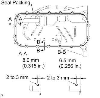 |
Apply continuous beads of seal packing to the places shown in the illustration.
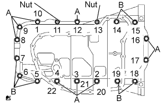 |
Loosely install the oil pan with the 16 bolts and 2 nuts.
Uniformly tighten the 16 bolts and 2 nuts in the sequence shown in the illustration.
| 13. INSTALL OIL STRAINER SUB-ASSEMBLY |
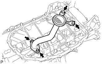 |
Install a new gasket and the oil strainer with the 2 bolts and 2 nuts.
| 14. INSTALL NO. 2 OIL PAN SUB-ASSEMBLY |
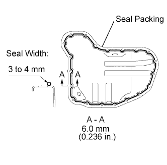 |
Apply continuous beads of seal packing to the places shown in the illustration.
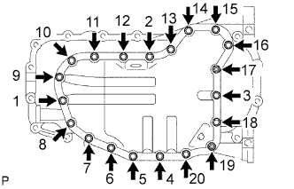 |
Provisionally install the oil pan with the 18 bolts and 2 nuts.
Uniformly tighten the 18 bolts and 2 nuts in the sequence shown in the illustration.
Install a new gasket and the drain plug.
| 15. INSTALL OIL LEVEL GAGE SUB-ASSEMBLY |
| 16. INSTALL CRANKSHAFT PULLEY |
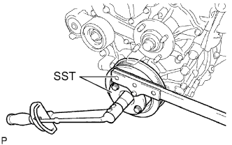 |
Align the set key of the crankshaft with the key groove of the pulley, and slide on the pulley.
Provisionally install a new crankshaft pulley bolt onto the crankshaft.
Using SST, hold the crankshaft pulley and tighten the crankshaft pulley bolt.
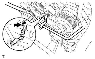 |
Install the bracket with the bolt. (w/ AIR CONDITIONING)
| 17. INSTALL CYLINDER HEAD COVER SUB-ASSEMBLY |
 |
Apply seal packing to the 2 locations shown in the illustration.
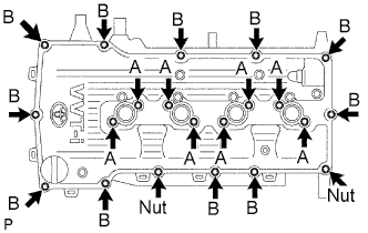 |
Provisionally install the cylinder head cover with the 19 bolts and 2 nuts.
Tighten bolts A shown in the illustration.
Tighten bolts B and nuts shown in the illustration.
Tighten bolts A again.
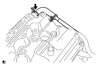 |
Connect the ventilation hose.
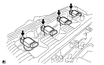 |
Install the ignition coils with the bolts.
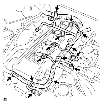 |
Install the engine wire harness clamps.
Connect the camshaft position sensor connector.
Connect the VSV connector.
Connect the throttle with motor body connector.
Connect the ignition coil connectors.
| 18. INSTALL NO. 1 INTAKE MANIFOLD TO HEAD GASKET |
|
Disconnect the ignition coil connectors.
Disconnect the throttle with motor body connector.
Disconnect the VSV connector.
Disconnect the camshaft position sensor connector.
Disconnect the engine wire harness clamps.
|
Remove the bolts, then remove the ignition coils.
|
Disconnect the ventilation hose.
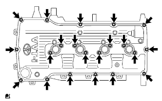 |
Remove the 19 bolts and 2 nuts, then remove the cylinder head cover.
| 19. INSTALL CAMSHAFT POSITION SENSOR |
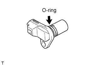 |
Apply a light coat of engine oil to the O-ring of the camshaft position sensor.
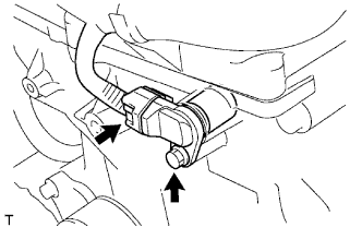 |
Install the camshaft position sensor with the bolt.
Connect the camshaft position sensor connector.
| 20. INSTALL CRANKSHAFT POSITION SENSOR |
|
Apply a light coat of engine oil to the O-ring of the camshaft position sensor.
|
Install the camshaft position sensor with the bolt.
Connect the camshaft position sensor connector.
| 21. INSTALL IDLE PULLEY ASSEMBLY WITH BRACKET (w/ Air Conditioning System) |
|
Disconnect the camshaft position sensor connector.
Remove the bolt, then remove the camshaft position sensor.
| 22. INSTALL NO. 1 IDLER PULLEY SUB-ASSEMBLY |
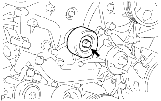 |
Install the No. 1 idler pulley sub-assembly with the bolt.
| 23. INSTALL V-RIBBED BELT TENSIONER ASSEMBLY |
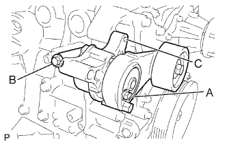 |
Provisionally install the V-ribbed belt tensioner with bolts A and B.
Tighten bolt B.
Tighten bolt A.
Check that the bolt holes of the V-ribbed belt tensioner and timing chain cover are aligned, and install bolt C.
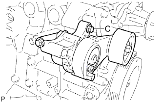 |
Tighten bolt C.
| 24. INSTALL GENERATOR ASSEMBLY |
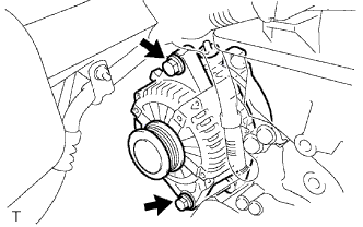 |
Install the generator with the 2 bolts.
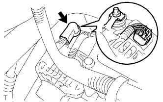 |
Connect the generator connector.
Install the generator wire with the nut.
Install the terminal cap.
| 25. INSTALL INTAKE AIR CONNECTOR |
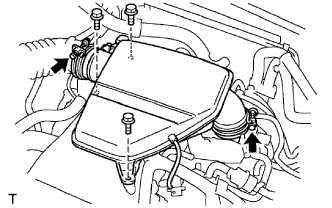 |
Install the intake air connector with the 3 bolts.
Tighten the 2 hose clamp bolts.
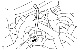 |
Connect the vacuum hose.
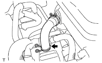 |
Connect the ventilation hose No. 2.
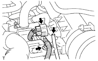 |
Connect the vacuum hose.
Engage the wire harness clamp.
Connect the pressure sensor connector.
| 26. INSTALL REAR END PLATE |
Install the rear end plate with the 2 bolts.
| 27. INSTALL DRIVE PLATE AND RING GEAR SUB-ASSEMBLY (for Automatic Transmission) |
 |
Clean the 10 bolts and 10 bolt holes.
Apply adhesive to 2 or 3 threads of the 10 bolts.
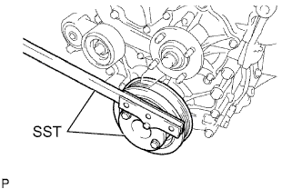
Provisionally install the drive plate spacer front, drive plate and ring gear and drive plate rear with the 10 bolts.
Using SST, hold the crankshaft.
 |
Using several steps, uniformly install and tighten the 10 bolts in the sequence shown in the illustration.
| 28. INSTALL FLYWHEEL SUB-ASSEMBLY (for Manual Transmission) |
|
Clean the 10 bolts and 10 bolt holes.
Apply adhesive to 2 or 3 threads of the 10 bolts.
Using SST, hold the crankshaft.
 |
Using several steps, uniformly install and tighten the 10 bolts in the sequence shown in the illustration.
 |
Mark the bolts with paint as shown in the illustration.
Retighten the bolts by 90° in the same sequence as in step (d).
Check that the paint mark of each bolt is at a 90° from the original position.
| 29. INSTALL CLUTCH DISC ASSEMBLY (for Manual Transmission) |
| Transmission | See page |
| R155 |
Click here
|
| R155F |
Click here
|
| 30. INSTALL CLUTCH COVER ASSEMBLY (for Manual Transmission) |
| Transmission | See page |
| R155 |
Click here
|
| R155F |
Click here
|
| 31. INSTALL ENGINE ASSEMBLY |
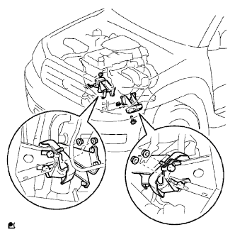 |
Attach the engine sling device and chain block to the engine hangers.
Keep the engine level, and align the engine mounting bracket front No. 1 RH w/ engine mounting insulator front and LH with the body mountings.
Attach the engine mounting bracket front No. 1 RH w/ engine mounting insulator front and LH, and install the 4 bolts and nuts.
Remove the bolts, then remove the engine hangers.
| 32. INSTALL AUTOMATIC TRANSMISSION ASSEMBLY (for Automatic Transmission) |
| Transmission | See page |
| A340E |
Click here
|
| A340F |
Click here
|
| 33. INSTALL MANUAL TRANSMISSION UNIT ASSEMBLY (for Manual Transmission) |
| Transmission | See page |
| R155 |
Click here
|
| R155F |
Click here
|
| 34. INSTALL EXHAUST PIPE ASSEMBLY FRONT |
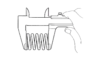 |
Check the free length.
Using vernier calipers, measure the free length of the compression spring.
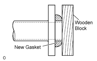 |
Using a wooden block and plastic-faced hammer, tap in a new gasket until it is flush with the exhaust manifold.
Install the exhaust pipe front into the exhaust pipe support.
Tighten the 2 bolts and 2 compression springs.
| 35. INSTALL EXHAUST PIPE ASSEMBLY TAIL |
Install a new gasket onto the exhaust pipe front.
Install the exhaust pipe tail onto the 4 exhaust pipe supports.
Tighten the 2 bolts and 2 nuts.
| 36. CONNECT ENGINE WIRE |
| 37. CONNECT NO. 1 AIR INJECTION HOSE |
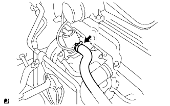 |
Connect the fuel vapor feed hose.
| 38. CONNECT FUEL VAPOR FEED HOSE ASSEMBLY |
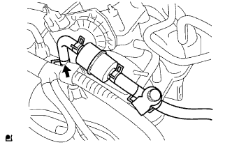 |
Connect the fuel feed hose.
| 39. CONNECT NO. 2 FUEL HOSE |
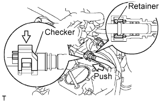 |
Align the fuel hose connector with the pipe stem, and insert the fuel hose until the retainer makes a "click" sound.
Push down the checker of the fuel hose.
Push the fuel hose down until the checker of the fuel hose makes a "click" sound.
| 40. CONNECT FUEL HOSE |
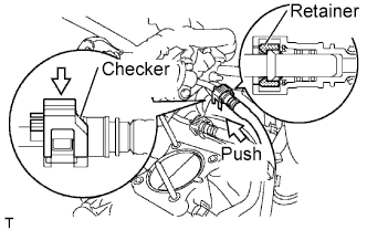 |
Align the fuel hose connector with the pipe stem, and insert the fuel hose until the retainer makes a "click" sound.
Push down the checker of the fuel hose.
Push the fuel hose down until the checker of the fuel hose makes a "click" sound.
| 41. INSTALL WATER HOSE SUB-ASSEMBLY |
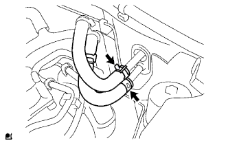 |
Install the water hose.
| 42. INSTALL RADIATOR HOSE INLET |
| 43. INSTALL COMPRESSOR AND MAGNETIC CLUTCH (w/ Air Conditioning System) |
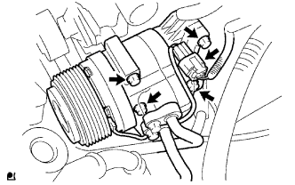 |
Install the compressor and magnetic clutch with the 4 bolts.
Connect the compressor and magnetic clutch connector.
|
Install the bolt shown in the illustration.
| 44. INSTALL NO. 2 RADIATOR HOSE |
| 45. INSTALL VANE PUMP ASSEMBLY |
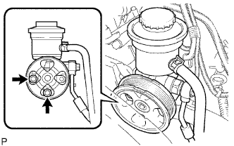 |
Install the vane pump with the 2 bolts.
Connect the vane pump connector.
| 46. INSTALL AIR CLEANER CASE |
Install the air cleaner case with the 3 bolts.
| 47. INSTALL AIR CLEANER FILTER ELEMENT SUB-ASSEMBLY |
| 48. INSTALL AIR CLEANER CAP SUB-ASSEMBLY |
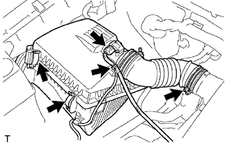 |
Install the air cleaner cap together with the air cleaner hose No. 1.
Connect the 2 air cleaner clamps.
Tighten the hose clamp bolt, then connect the air cleaner hose No. 1.
Connect the wire harness clamp.
Connect the mass air flow meter connector.
| 49. INSTALL FAN SHROUD |
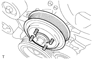 |
Install the fan pulley.
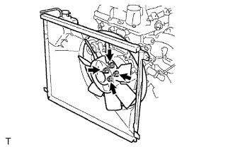 |
Install the fan shroud and fan with fluid coupling together.
Provisionally install the fan with fluid coupling with the 4 nuts.
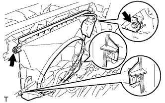 |
Install the 2 bolts shown in the illustration.
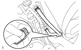 |
Connect the oil cooler inlet and outlet hoses to the fan shroud. (for Automatic Transmission)
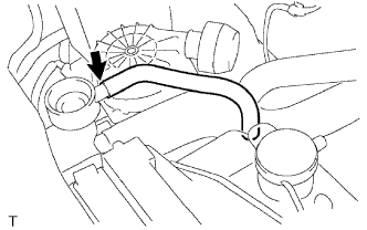 |
Connect the radiator reserve tank hose to the radiator.
Install the fan generator V belt.
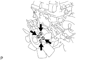 |
Tighten the 4 nuts shown in the illustration.
| 50. INSTALL RADIATOR SUPPORT TO FRAME SEAL LH |
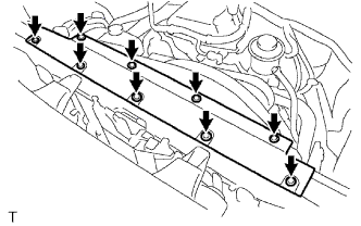 |
Install the radiator support frame seal LH with the 9 clips.
| 51. INSTALL BATTERY TRAY |
| 52. INSTALL BATTERY |
| 53. ADD ENGINE OIL |
Fill with fresh engine oil.
| Oil grade | Oil viscosity (SAE) |
| ILSAC multigrade engine oil | 0W-20 |
| Item | Specified Condition |
| Drain and refill with oil filter change | 5.8 liters (6.1 US qts, 5.1 Imp. qts) |
| Drain and refill without oil filter change | 5.1 liters (5.4 US qts, 4.5 Imp. qts) |
| Dry fill | 6.1 liters (6.4 US qts, 5.4 Imp. qts) |
| 54. ADD ENGINE COOLANT |
Tighten the engine drain plug.
Tighten the radiator drain plug.
Disconnect the 2 vinyl hoses.
Slowly fill the system with engine coolant.
Check the coolant level inside the radiator by squeezing the inlet and outlet radiator hoses several times by hand. If the coolant level goes down, add coolant.
Install the radiator cap securely.
Slowly pour coolant into the radiator reservoir until it reaches the FULL line.
Warm up the engine until the cooling fan operates.
| Item | Condition |
| Fan speed | Any setting except OFF |
| Temperature | Toward warm |
| Air condition switch | OFF |
Squeeze the inlet and outlet radiator hoses several times by hand while warning up the engine.
Stop the engine and wait until the coolant cools down.
Remove the radiator cap and check the coolant level inside the radiator.
If the coolant level is below the full level, perform the steps from (d) through (k) and repeat the operation until the coolant level remains at the full level.
Check the coolant level inside the radiator reservoir tank again. If it is below the full level, add coolant.
Install the engine under cover No. 1 with the 4 bolts. (PRE RUNNER AND 4WD TYPE)
| 55. CHECK FOR ENGINE OIL LEVEL |
| 56. CHECK FOR FUEL LEAKAGE |
| 57. CHECK FOR ENGINE COOLANT LEAKAGE |
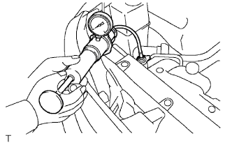 |
Fill the radiator with coolant and attach a radiator cap tester.
Warm up the engine.
Pump it up to 118 kPa (1.2 kgf/cm2, 17.1 psi) and check that the pressure does not drop.
| 58. CHECK FOR OIL LEAKAGE |
| 59. CHECK FOR EXHAUST GAS LEAKAGE |
| 60. INSTALL NO. 1 ENGINE UNDER COVER SUB-ASSEMBLY (for 4WD and Pre-Runner) |
Install the No. 1 engine under cover with the 4 bolts.
| 61. INSTALL NO. 2 ENGINE UNDER COVER SUB-ASSEMBLY (for 4WD and Pre-Runner, Regular Cab) |
Install the No. 2 engine under cover with the 4 bolts.
| 62. INSTALL HOOD SUB-ASSEMBLY |