 |
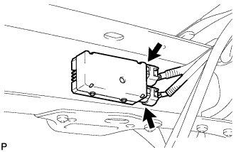
Disconnect the 2 fuel pump ECU connectors.
VALVE CLEARANCE > ADJUSTMENT |
| 1. DISCHARGE FUEL SYSTEM PRESSURE |
Disconnect the cable from the negative (-) battery terminal.
|
Disconnect the 2 fuel pump ECU connectors.
Connect the cable to the negative (-) battery terminal.
Start the engine. After the engine has stopped on its own, turn the ignition switch OFF.
Crank the engine again, then check that the engine does not start.
Loosen the fuel tank cap, then discharge the pressure in the fuel tank completely.
Connect the 2 fuel pump ECU connectors.
| 2. DISCONNECT CABLE FROM NEGATIVE BATTERY TERMINAL |
| 3. REMOVE THROTTLE BODY COVER SUB-ASSEMBLY |
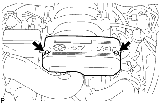 |
Remove the 2 nuts and throttle body cover.
| 4. REMOVE AIR CLEANER HOSE ASSEMBLY |
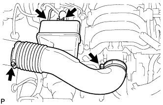 |
Disconnect the vacuum hose and No. 2 ventilation hose.
Loosen the 2 hose clamps.
Remove the air cleaner hose.
| 5. REMOVE AIR SWITCHING VALVE ASSEMBLY (for Bank 1) |
Remove the air switching valve .
| 6. REMOVE AIR SWITCHING VALVE ASSEMBLY (for Bank 2) |
Remove the air switching valve .
| 7. REMOVE IGNITION COIL ASSEMBLY |
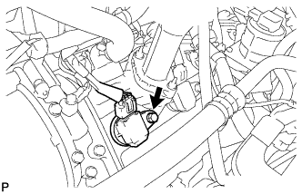 |
Disconnect the 8 ignition coil connectors.
Remove the 8 bolts and pull out the 8 ignition coils.
| 8. REMOVE FAN AND GENERATOR V BELT |
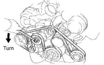 |
Loosen the belt tension by turning the belt tensioner counterclockwise, and then remove the fan and generator V belt.
| 9. REMOVE NO. 3 TIMING BELT COVER SUB-ASSEMBLY LH |
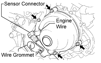 |
Disconnect the engine wire from the 2 wire clamps.
Disconnect the camshaft position sensor connector.
Disconnect the camshaft position sensor wire from the wire clamp on the timing belt cover.
Remove the wire grommet from the timing belt cover.
Remove the 4 bolts.
Pull the cover outward, pull the camshaft position sensor wire out of the cover, and remove the cover.
| 10. REMOVE NO. 3 TIMING BELT COVER SUB-ASSEMBLY RH |
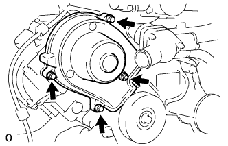 |
Remove the 3 bolts, nut and timing belt cover.
| 11. REMOVE CYLINDER HEAD COVER SUB-ASSEMBLY RH |
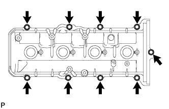 |
Remove the 9 bolts, cylinder head cover and gasket.
| 12. REMOVE CYLINDER HEAD COVER SUB-ASSEMBLY LH |
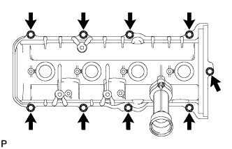 |
Remove the 9 bolts, cylinder head cover and gasket.
| 13. SET NO. 1 CYLINDER TO TDC / COMPRESSION |
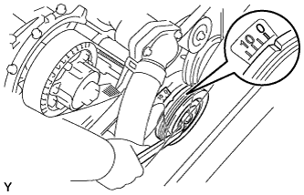 |
Turn the crankshaft pulley to align its notch with timing mark "0" of the No. 1 timing belt cover.
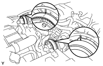 |
Check that the timing marks of the camshaft timing pulleys and timing belt rear plates are aligned.
If not, turn the crankshaft 1 complete revolution (360°) and align the marks as above.
| 14. INSPECT VALVE CLEARANCE |
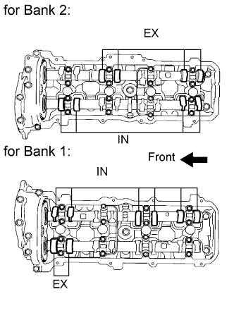 |
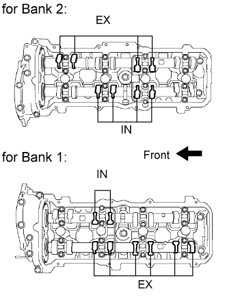
Check only the valves indicated.
Using a feeler gauge, measure the clearance between the valve lifter and camshaft.
| Item | Specified Condition |
| Intake | 0.15 to 0.25 mm (0.00591 to 0.00984 in.) |
| Exhaust | 0.25 to 0.35 mm (0.00984 to 0.0138 in.) |
Record the out-of-specification valve clearance measurements. They will be used later to determine the required replacement adjusting shim.
 |
Turn the crankshaft 1 complete revolution (360°) and align the camshaft timing marks.
Check only the valves indicated in the illustration.
Using a feeler gauge, measure the clearance between the valve lifter and camshaft.
| Item | Specified Condition |
| Intake | 0.15 to 0.25 mm (0.00591 to 0.00984 in) |
| Exhaust | 0.25 to 0.35 mm (0.00984 to 0.0138 in.) |
Record the out-of-specification valve clearance measurements. They will be used later to determine the required replacement adjusting shim.
| 15. ADJUST VALVE CLEARANCE |
Remove the timing belt (Click here).
Remove the camshaft LH .
Remove the camshaft RH .
Remove the valve lifter and adjusting shim.
 |
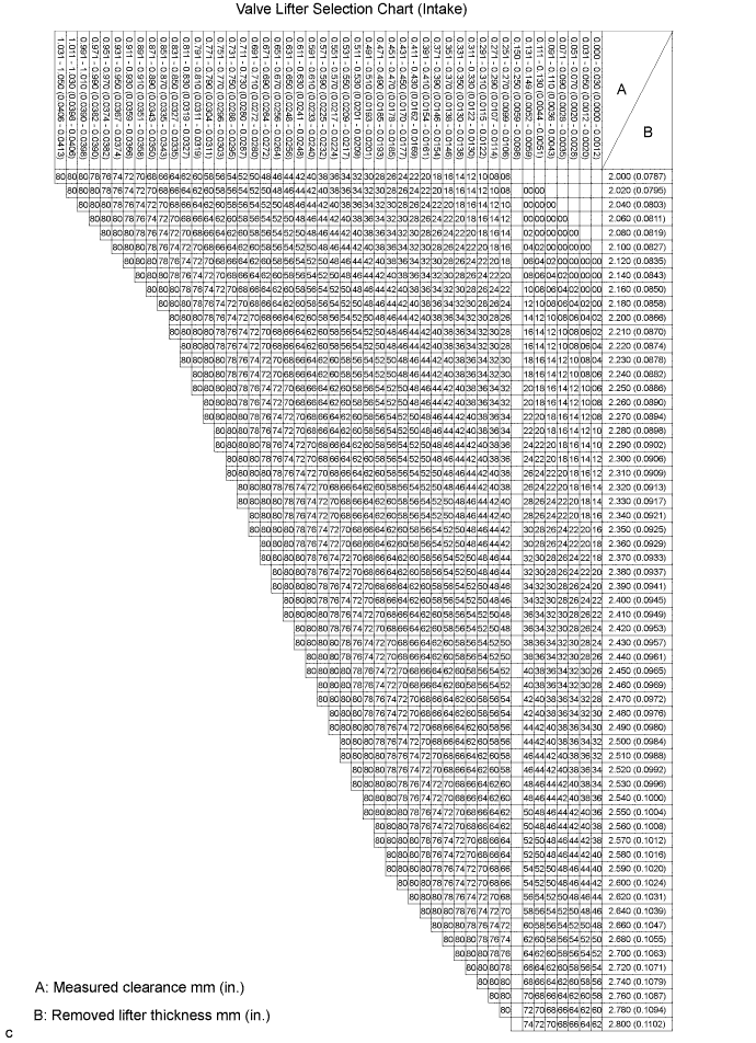
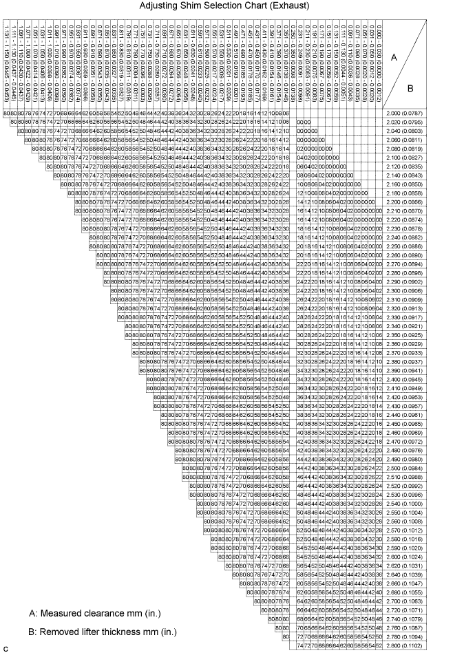
Determine the replacement adjusting shim size according to the formula or charts below.
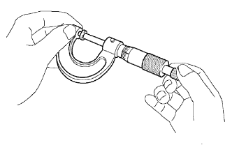
Using a micrometer, measure the thickness of the removed shim.
Calculate the thickness of a new shim so that the valve clearance comes within the specified value.
Select a new shim with a thickness as close as possible to the calculated value.
| Shim No. | Thickness | Shim No. | Thickness | Shim No. | Thickness |
| 00 | 2.000 mm (0.0787 in.) | 28 | 2.280 mm (0.0898 in.) | 56 | 2.560 mm (0.1008 in.) |
| 02 | 2.020 mm (0.0795 in.) | 30 | 2.300 mm (0.0906 in.) | 58 | 2.580 mm (0.1016 in.) |
| 04 | 2.040 mm (0.0803 in.) | 32 | 2.320 mm (0.0913 in.) | 60 | 2.600 mm (0.1024 in.) |
| 06 | 2.060 mm (0.0811 in.) | 34 | 2.340 mm (0.0921 in.) | 62 | 2.620 mm (0.1031 in.) |
| 08 | 2.080 mm (0.0819 in.) | 36 | 2.360 mm (0.0929 in.) | 64 | 2.640 mm (0.1039 in.) |
| 10 | 2.100 mm (0.0827 in.) | 38 | 2.380 mm (0.0937 in.) | 66 | 2.660 mm (0.1047 in.) |
| 12 | 2.120 mm (0.0835 in.) | 40 | 2.400 mm (0.0945 in.) | 68 | 2.680 mm (0.1055 in.) |
| 14 | 2.140 mm (0.0843 in.) | 42 | 2.420 mm (0.0953 in.) | 70 | 2.700 mm (0.1063 in.) |
| 16 | 2.160 mm (0.0850 in.) | 44 | 2.440 mm (0.0961 in.) | 72 | 2.720 mm (0.1071 in.) |
| 18 | 2.180 mm (0.0858 in.) | 46 | 2.460 mm (0.0969 in.) | 74 | 2.740 mm (0.1079 in.) |
| 20 | 2.200 mm (0.0866 in.) | 48 | 2.480 mm (0.0976 in.) | 76 | 2.760 mm (0.1087 in.) |
| 22 | 2.220 mm (0.0874 in.) | 50 | 2.500 mm (0.0984 in.) | 78 | 2.780 mm (0.1094 in.) |
| 24 | 2.240 mm (0.0882 in.) | 52 | 2.520 mm (0.0992 in.) | 80 | 2.800 mm (0.1102 in.) |
| 26 | 2.260 mm (0.0890 in.) | 54 | 2.540 mm (0.1000 in.) | - | - |
| Shim No. | Thickness | Shim No. | Thickness | Shim No. | Thickness |
| 00 | 2.000 mm (0.0787 in.) | 28 | 2.280 mm (0.0898 in.) | 56 | 2.560 mm (0.1008 in.) |
| 02 | 2.020 mm (0.0795 in.) | 30 | 2.300 mm (0.0906 in.) | 58 | 2.580 mm (0.1016 in.) |
| 04 | 2.040 mm (0.0803 in.) | 32 | 2.320 mm (0.0913 in.) | 60 | 2.600 mm (0.1024 in.) |
| 06 | 2.060 mm (0.0811 in.) | 34 | 2.340 mm (0.0921 in.) | 62 | 2.620 mm (0.1031 in.) |
| 08 | 2.080 mm (0.0819 in.) | 36 | 2.360 mm (0.0929 in.) | 64 | 2.640 mm (0.1039 in.) |
| 10 | 2.100 mm (0.0827 in.) | 38 | 2.380 mm (0.0937 in.) | 66 | 2.660 mm (0.1047 in.) |
| 12 | 2.120 mm (0.0835 in.) | 40 | 2.400 mm (0.0945 in.) | 68 | 2.680 mm (0.1055 in.) |
| 14 | 2.140 mm (0.0843 in.) | 42 | 2.420 mm (0.0953 in.) | 70 | 2.700 mm (0.1063 in.) |
| 16 | 2.160 mm (0.0850 in.) | 44 | 2.440 mm (0.0961 in.) | 72 | 2.720 mm (0.1071 in.) |
| 18 | 2.180 mm (0.0858 in.) | 46 | 2.460 mm (0.0969 in.) | 74 | 2.740 mm (0.1079 in.) |
| 20 | 2.200 mm (0.0866 in.) | 48 | 2.480 mm (0.0976 in.) | 76 | 2.760 mm (0.1087 in.) |
| 22 | 2.220 mm (0.0874 in.) | 50 | 2.500 mm (0.0984 in.) | 78 | 2.780 mm (0.1094 in.) |
| 24 | 2.240 mm (0.0882 in.) | 52 | 2.520 mm (0.0992 in.) | 80 | 2.800 mm (0.1102 in.) |
| 26 | 2.260 mm (0.0890 in.) | 54 | 2.540 mm (0.1000 in.) | - | - |
Place a new adjusting shim on the valve.
Place the valve lifter.
Install the camshaft LH .
Install the camshaft RH .
Install the timing belt (Click here).
Check the valve clearance.
If the result is not as specified, adjust the valve clearance.
| 16. INSTALL CYLINDER HEAD COVER SUB-ASSEMBLY LH |
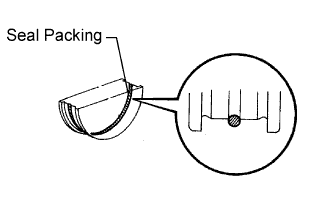 |
Apply seal packing to the semicircular plug grooves.
Install the 2 semicircular plugs to the cylinder heads.
Install the gasket to the cylinder head cover.
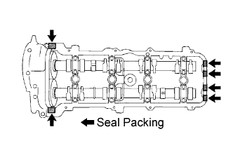 |
Apply seal packing to the cylinder head as shown in the illustration.
|
Install the cylinder head cover with the 9 bolts. Uniformly tighten the bolts in several steps.
| 17. INSTALL CYLINDER HEAD COVER SUB-ASSEMBLY RH |
|
Apply seal packing to the semicircular plug grooves.
Install the 2 semicircular plugs to the cylinder heads.
Install the gasket to the cylinder head cover.
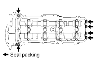 |
Apply seal packing to the cylinder head as shown in the illustration.
|
Install the cylinder head cover with the 9 bolts. Uniformly tighten the bolts in several steps.
| 18. INSTALL NO. 3 TIMING BELT COVER SUB-ASSEMBLY RH |
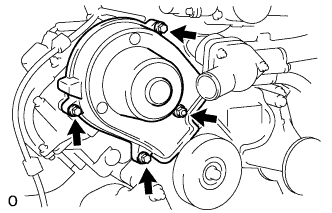 |
Install the cover with the 3 bolts and nut.
| 19. INSTALL NO. 3 TIMING BELT COVER SUB-ASSEMBLY LH |
|
Pass the camshaft position sensor wire through the cover hole.
Install the cover with the 4 bolts.
Install the wire grommet to the belt cover.
Connect the sensor connector.
Install the sensor wire to the wire clamps on the cover.
Connect the engine wire to the 2 wire clamps on the cover.
| 20. INSTALL IGNITION COIL ASSEMBLY |
|
Install the 8 ignition coils with the 8 bolts.
Connect the 8 ignition coil connectors.
| 21. INSTALL AIR SWITCHING VALVE ASSEMBLY (for Bank 1) |
Install the air switching valve (Click here).
| 22. INSTALL AIR SWITCHING VALVE ASSEMBLY (for Bank 2) |
Install the air switching valve (Click here).
| 23. INSTALL FAN AND GENERATOR V BELT |
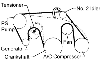 |
Set the V belt onto every part except the No. 2 idler pulley, as shown in the illustration.
Loosen the V belt by turning the belt tensioner counterclockwise.
Set the V belt to the No. 2 idler pulley.
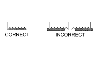 |
After installing the belt, check that it fits properly in the ribbed grooves.
Check by hand to confirm that the belt has not slipped out of the grooves on the bottom of the pulley.
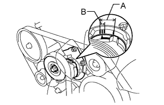 |
Check that the arrow on the belt tensioner is within area "A".
If it is outside area "A", replace the fan and generator V belt.
| 24. INSTALL AIR CLEANER HOSE ASSEMBLY |
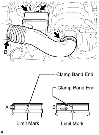 |
Install the air cleaner hose.
Connect the vacuum hose.
Connect the No. 2 ventilation hose.
| 25. INSTALL THROTTLE BODY COVER SUB-ASSEMBLY |
|
Install the throttle body cover sub-assembly with the 2 nuts.
| 26. CONNECT CABLE TO NEGATIVE BATTERY TERMINAL |