3UR-FBE EXHAUST EXHAUST PIPE INSTALLATION
PROCEDURE

 89467B
1.INSTALL AIR FUEL RATIO SENSOR (for Bank 2 Sensor 1)
89465
2.INSTALL HEATED OXYGEN SENSOR (for Bank 2 Sensor 2)
17410
3.INSTALL FRONT EXHAUST PIPE ASSEMBLY
Install a new gasket and the front exhaust pipe assembly to the exhaust manifold sub-assembly RH with 3 new nuts.
- Torque:
- 54 N*m (554 kgf*cm, 40 ft.*lbf)
89467B
4.INSTALL AIR FUEL RATIO SENSOR (for Bank 1 Sensor 1)
89465
5.INSTALL HEATED OXYGEN SENSOR (for Bank 1 Sensor 2)
17450B
6.INSTALL FRONT NO. 2 EXHAUST PIPE ASSEMBLY
Connect the front No. 2 exhaust pipe assembly to the exhaust pipe support.
Install a new gasket and the front No. 2 exhaust pipe assembly to the exhaust manifold sub-assembly LH with 3 new nuts.
- Torque:
- 54 N*m (554 kgf*cm, 40 ft.*lbf)
37140
7.INSTALL FRONT PROPELLER SHAFT ASSEMBLY
17420
8.INSTALL CENTER EXHAUST PIPE ASSEMBLY
Connect the center exhaust pipe assembly to the 3 exhaust pipe supports.
Install 2 new gaskets to the front exhaust pipe assembly and front No. 2 exhaust pipe assembly.
Install the center exhaust pipe assembly with the 4 bolts.
- Torque:
- 48 N*m (489 kgf*cm, 35 ft.*lbf)
17430
9.INSTALL TAILPIPE ASSEMBLY
Connect the tailpipe assembly to the exhaust pipe support.
Install a new gasket to the center exhaust pipe assembly.
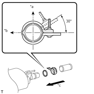
Attach a new clamp to the tailpipe assembly and center exhaust pipe assembly. Then install the bolt to the clamp.
- Torque:
- 32 N*m (326 kgf*cm, 24 ft.*lbf)
- HINT:
-
Install the clamp within the angle range shown in the illustration.
| *a | Top |
| *b | LH Side of Vehicle |
| *c | Front Side of Vehicle |
10.INSPECT FOR EXHAUST GAS LEAK