WF1AM TRANSFER TOUCH SELECT 2-4 AND HIGH-LOW SYSTEM P17AC Transfer Shift Motor Limit Switch Circuit
DESCRIPTION
This DTC is detected when a malfunction is detected in the limit switch circuit, which detects the position of the transfer shift motor.
| DTC Code | DTC Detection Condition
1.
Diagnosis Condition 2.
Malfunction Status 3.
Malfunction Time 4.
Other |
Trouble Area |
|---|---|---|
| P17AC | 1.
When the ignition switch is ON, the engine is running, and the driving mode is being switched 2.
The combination of the TL1, TL2, TL3 and TL4 terminal signals is abnormal or the TL1, TL2, TL3 and TL4 terminal signal switching order is abnormal 3.
0.02 seconds or more 4.
1 trip detection logic |
·
Wire harness and connector ·
4 wheel drive control ECU ·
Transfer shift actuator assembly |
WIRING DIAGRAM
Refer to DTC P17AB (See page Drivetrain>WF1AM TRANSFER>TOUCH SELECT 2-4 AND HIGH-LOW SYSTEM>P17AB).
PROCEDURE
Disconnect the A26 4 wheel drive control ECU connector.
Disconnect the D68 transfer shift actuator assembly connector.
Measure the resistance according to the value(s) in the table below.
- Standard Resistance:
Tester Connection Condition Specified Condition A26-18 (TL1) - D68-1 (TL1) Always Below 1 Ω A26-20 (TL2) - D68-2 (TL2) Always Below 1 Ω A26-26 (TL3) - D68-3 (TL3) Always Below 1 Ω A26-24 (TL4) - D68-4 (TL4) Always Below 1 Ω A26-22 (GTL) - D68-5 (GTL) Always Below 1 Ω A26-18 (TL1) or D68-1 (TL1) - Body ground Always 10 kΩ or higher A26-20 (TL2) or D68-2 (TL2) - Body ground Always 10 kΩ or higher A26-26 (TL3) or D68-3 (TL3) - Body ground Always 10 kΩ or higher A26-24 (TL4) or D68-4 (TL4) - Body ground Always 10 kΩ or higher A26-18 (TL1) - D68-2 (TL2), D68-3 (TL3), D68-4 (TL4) and D68-5 (GTL) Always 10 kΩ or higher A26-20 (TL2) - D68-1 (TL1), D68-3 (TL3), D68-4 (TL4) and D68-5 (GTL) Always 10 kΩ or higher A26-26 (TL3) - D68-1 (TL1), D68-2 (TL2), D68-4 (TL4) and D68-5 (GTL) Always 10 kΩ or higher A26-24 (TL4) - D68-1 (TL1), D68-2 (TL2), D68-3 (TL3) and D68-5 (GTL) Always 10 kΩ or higher
OK
NG
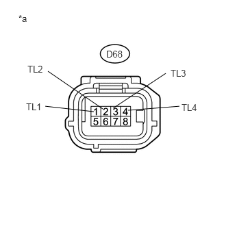
Disconnect the transfer shift actuator assembly connector.
Measure the voltage according to the value(s) in the table below.
- Standard Voltage:
Tester Connection Switch Condition Specified Condition D68-1 (TL1) - Body ground Ignition switch ON 4 to 6 V D68-2 (TL2) - Body ground Ignition switch ON 4 to 6 V D68-3 (TL3) - Body ground Ignition switch ON 4 to 6 V D68-4 (TL4) - Body ground Ignition switch ON 4 to 6 V
| *a | Front view of wire harness connector
(to Transfer Shift Actuator Assembly) |
OK
NG