DRIVE SHAFT FRONT DRIVE SHAFT ASSEMBLY(for 4WD) INSTALLATION
CAUTION / NOTICE / HINT
- HINT:
- ·
Use the same procedures for the RH side and LH side.
·The procedures listed below are for the LH side.
·A bolt without a torque specification is shown in the standard bolt chart (see page General>SPECIFICATIONS>STANDARD BOLT>SPECIFIED TORQUE FOR STANDARD BOLTS).
PROCEDURE

 43420
1.INSTALL FRONT DRIVE SHAFT ASSEMBLY LH (for Front Differential Side)
Install a new snap ring to the inboard joint shaft.
Coat the spline of the inboard joint shaft assembly with gear oil.
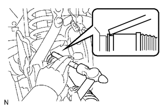
Align the shaft splines and install the drive shaft with a brass bar and hammer.
- NOTICE:
- ·
Set the snap ring with the opening side facing downward.
·Be careful not to damage the oil seal.
- HINT:
-
Whether the inboard joint shaft is in contact with the pinion shaft or not can be confirmed from the sound or feeling when driving it.
43420
2.INSTALL FRONT DRIVE SHAFT ASSEMBLY LH (for Axle Hub Side)
Install the drive shaft to the steering knuckle.
- NOTICE:
-
Be careful not to damage the oil seal, boots and dust seal.
48626
3.CONNECT FRONT LOWER BALL JOINT ATTACHMENT
45047
4.INSTALL TIE ROD END SUB-ASSEMBLY
42601C
5.INSTALL AXLE HUB NUT
43514C
6.INSTALL FRONT AXLE HUB GREASE CAP
89543
7.INSTALL FRONT SPEED SENSOR LH
Install the front speed sensor (see page Brake>BRAKE CONTROL / DYNAMIC CONTROL SYSTEMS>FRONT SPEED SENSOR>INSTALLATION).
51441
8.INSTALL NO. 1 ENGINE UNDER COVER
9.INSTALL FRONT WHEEL
Install the front wheels.
- Torque:
- for aluminum wheel : 131 N*m (1336 kgf*cm, 97 ft.*lbf)
- for steel wheel : 209 N*m (2131 kgf*cm, 154 ft.*lbf)
10.ADD DIFFERENTIAL OIL
11.CHECK SPEED SENSOR SIGNAL
Check the speed sensor signal (see page Brake>BRAKE CONTROL / DYNAMIC CONTROL SYSTEMS>FRONT SPEED SENSOR>INSTALLATION).
12.CHECK FOR DIFFERENTIAL OIL LEAK
13.INSPECT AND ADJUST FRONT WHEEL ALIGNMENT
Inspect and adjust the front wheel alignment (see page Suspension>SUSPENSION>FRONT WHEEL ALIGNMENT>ADJUSTMENT).