BRAKE CONTROL / DYNAMIC CONTROL SYSTEMS VEHICLE STABILITY CONTROL SYSTEM C1232/32 Stuck in Deceleration Sensor C1234/34 Yaw Rate Sensor Malfunction C1244/44 Open or Short in Deceleration Sensor Circuit C1279/79 Deceleration Sensor Output Voltage Malfunction (Test Mode DTC)
DESCRIPTION
The skid control ECU receives signals from the yaw rate and deceleration sensor via the CAN communication system.
The yaw rate sensor has a built-in deceleration sensor.
If there is trouble in the bus lines between the yaw rate and deceleration sensor and skid control ECU, DTC U0123/62 (malfunction in CAN communication with the yaw rate sensor) and U0124/69 (malfunction in CAN communication with the deceleration sensor) are output.
DTC C1279/79 is deleted when the yaw rate sensor sends a deceleration signal failure in test mode. DTC C1279/79 is using only in test mode.
| DTC Code | DTC Detection Condition | Trouble Area |
|---|---|---|
| C1232/32 | When any of following conditions detected:
1.
Malfunctions in deceleration sensor detected through self-diagnosis. 2.
Malfunctions in deceleration sensor circuit detected. 3.
Power supply to deceleration sensor abnormal (less than 6.5 V or 18 V or more). 4.
When ignition switch turned ON, short between deceleration sensor power supply and either ground or battery. |
·
Yaw rate sensor ·
Yaw rate sensor circuit ·
Skid control ECU |
| C1234/34 | Sensor malfunction signal received from yaw rate sensor | ·
Yaw rate sensor ·
Yaw rate sensor circuit ·
Skid control ECU |
| C1244/44 | G sensor forward and backward operation is malfunctioning (4WD) | ·
Yaw rate sensor ·
Yaw rate sensor circuit ·
Skid control ECU |
| C1279/79 | Detected only during test mode | ·
Yaw rate sensor ·
Yaw rate sensor circuit ·
Skid control ECU |
WIRING DIAGRAM
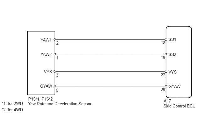
CAUTION / NOTICE / HINT
- HINT:
-
When U0123/62, U0124/69 or U0126/63 is output together with C1232/32, C1234/34 or C1244/44, inspect and repair the trouble areas indicated by U0123/62, U0124/69 or U0126/63 first.
- NOTICE:
-
When replacing the VSC actuator assembly, perform zero point calibration (See page Brake>BRAKE CONTROL / DYNAMIC CONTROL SYSTEMS>VEHICLE STABILITY CONTROL SYSTEM>CALIBRATION).
PROCEDURE
Clear the DTC(s) (See page Brake>BRAKE CONTROL / DYNAMIC CONTROL SYSTEMS>VEHICLE STABILITY CONTROL SYSTEM>DTC CHECK / CLEAR).
Turn the ignition switch off.
Turn the ignition switch to ON again and check that no CAN communication system DTC(s) is output.
Drive the vehicle at a speed of 30 km/h (19 mph) or more and check that no DTCs are output.
| Result | Proceed to |
|---|---|
| DTC is output (relating to yaw rate and deceleration sensor) | A |
| DTC is output (relating to CAN communication system) | B |
| DTC is not output | C |
A
B
(See pagePower Source / Network>CAN COMMUNICATION>CAN COMMUNICATION SYSTEM>DIAGNOSTIC TROUBLE CODE CHART)
C
(See pageGeneral>INTRODUCTION>HOW TO TROUBLESHOOT ECU CONTROLLED SYSTEMS>HOW TO PROCEED WITH TROUBLESHOOTING)
Check that the yaw rate sensor has been installed correctly (See page Brake>BRAKE CONTROL / DYNAMIC CONTROL SYSTEMS>YAW RATE AND DECELERATION SENSOR>INSTALLATION).
- OK:
The sensor is tightened to the specified torque.
The sensor is not tilted.
- NOTICE:
-
Do not use an electric impact wrench to tighten the yaw rate and deceleration sensor bolts because the sensor is sensitive to vibration.
OK
NG
(See pageBrake>BRAKE CONTROL / DYNAMIC CONTROL SYSTEMS>YAW RATE AND DECELERATION SENSOR>INSTALLATION)
Remove the 2 nuts of the sensor bracket and yaw rate sensor with the connector connected (See page Brake>BRAKE CONTROL / DYNAMIC CONTROL SYSTEMS>YAW RATE AND DECELERATION SENSOR>REMOVAL).
Connect the Techstream to the DLC3.
Turn the Techstream on.
Select the Data List mode on the Techstream.
| Tester Display | Measurement Item/Range | Normal Condition | Diagnostic Note |
|---|---|---|---|
| Deceleration Sensor2 | Acceleration sensor 2 reading /
min.: -18.525 m/s2, max.: 18.387 m/s2 |
Approximately -1.280 to 1.270 m/s2
while stationary |
Reading changes when vehicle is bounced. |
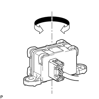
Place the yaw rate sensor as shown in the illustration and turn the sensor to the right and left.
Check that the deceleration value of the deceleration sensor displayed on the Techstream changes.
- OK:
Deceleration value changes.
OK
NG
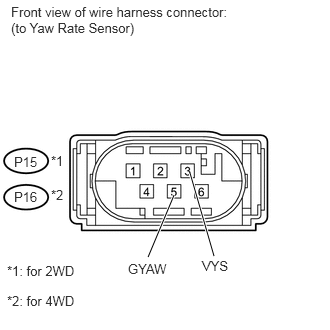
for 2WD:
Disconnect the P15 sensor connector.
for 4WD:
Disconnect the P16 sensor connector.
Measure the voltage according to the value(s) in the table below.
- Standard Voltage:
- for 2WD:
Tester Connection Switch Condition Specified Condition P15-3 (VYS) - P15-5 (GYAW) Ignition switch ON 11 to 14 V
- for 4WD:
Tester Connection Switch Condition Specified Condition P16-3 (VYS) - P16-5 (GYAW) Ignition switch ON 11 to 14 V
Measure the resistance according to the value(s) in the table below.
- Standard Resistance:
- for 2WD:
Tester Connection Switch Condition Specified Condition P15-5 (GYAW) - Body ground Ignition switch ON Below 1 Ω
- for 4WD:
Tester Connection Switch Condition Specified Condition P16-5 (GYAW) - Body ground Ignition switch ON Below 1 Ω
OK
NG