Home › Vehicle Interior › ENGINE IMMOBILISER › ENGINE IMMOBILISER SYSTEM
RM27M0U _58 Vehicle Interior _049156 ENGINE IMMOBILISER _0234432 ENGINE IMMOBILISER SYSTEM C

ENGINE IMMOBILISER  ENGINE IMMOBILISER SYSTEM  B279A  Theft Deterrent System Communication Line High Fixation  


DESCRIPTION

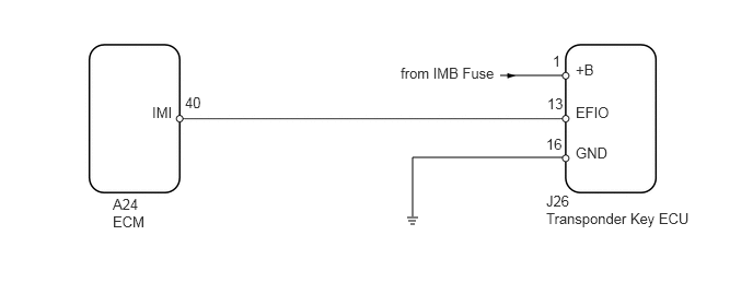
If the communication line (EFIO-IMI) to the transponder key ECU is stuck on HI output, the ECM outputs this DTC.

DTC Code DTC Detection Condition Trouble Area
B279A When communication line (EFIO-IMI) between ECM and transponder key ECU is stuck on HI output for 6 seconds or more
·

Harness or connector

·

Transponder key ECU

·

ECM


WIRING DIAGRAM

U151879E02
4.76,0.719 5.354,0.719 false 5.354,1.5 3.927,1.5 3.927,1.5 3.927,2.063 false 3.875,2.073 3.979,2.073 false 3.885,2.104 3.958,2.104 false 3.906,2.135 3.948,2.135 false 1.073,1.865 1.552,2.208 0.479,0.344 10 false A24 ECM 5.198,2 6.698,2.427 1.5,0.427 10 false Transponder Key ECU 1.448,0.99 1.771,1.188 0.323,0.198 10 false IMI 1.76,0.896 1.948,1.052 0.188,0.156 10 false 40 3.813,0.615 4.771,0.813 0.958,0.198 10 false from IMB Fuse 5.208,0.906 5.427,1.083 0.219,0.177 10 false 13 5.479,0.99 5.854,1.188 0.375,0.198 10 false EFIO 5.479,0.583 5.854,0.781 0.375,0.198 10 false +B 5.26,0.5 5.417,0.677 0.156,0.177 10 false 1 5.479,1.375 5.854,1.573 0.375,0.198 10 false GND 5.198,1.292 5.406,1.469 0.208,0.177 10 false 16 5.198,1.833 5.656,2.031 0.458,0.198 10 false J26

CAUTION / NOTICE / HINT

NOTICE:

Inspect the fuses for circuits related to this system before performing the following inspection procedure.


PROCEDURE

1.CLEAR DTC

NEXT

2.CHECK FOR DTC
2.CHECK FOR DTC
a.

Check for DTC (see page Vehicle Interior>ENGINE IMMOBILISER>ENGINE IMMOBILISER SYSTEM>DTC CHECK / CLEAR).

Result
Result Proceed to
DTC B279A is output A
DTC B279A and other DTCs are output B

HINT:

If any DTCs other than B279A are output, troubleshoot those DTCs first.


A

3.CHECK HARNESS AND CONNECTOR (TRANSPONDER KEY ECU - ECM)

B

3.CHECK HARNESS AND CONNECTOR (TRANSPONDER KEY ECU - ECM)
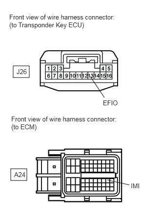
a.
B443048E02
0.281,1.406 0.625,1.656 0.344,0.25 0.229,3.604 0.573,3.854 0.344,0.25 1.927,1.635 2.229,2.083 false 2.292,3.844 2.76,3.948 false 0.198,0.281 2.448,0.656 2.25,0.375 10 false Front view of wire harness connector: (to Transponder Key ECU) 0.24,2.458 2.5,2.833 2.26,0.375 10 false Front view of wire harness connector: (to ECM) 0.354,1.448 0.813,1.646 0.458,0.198 10 false J26 0.302,3.646 0.76,3.844 0.458,0.198 10 false A24 2.198,2.115 2.813,2.313 0.615,0.198 10 false EFIO 2.792,3.885 3.25,4.083 0.458,0.198 10 false IMI

Disconnect the J26 ECU connector.


b.

Disconnect the A24 ECM connector.


c.

Measure the resistance and voltage according to the value(s) in the table below.

Standard resistance:
Tester Connection Condition Specified Condition
J26-13 (EFIO) - A24-40 (IMI) Always Below 1 Ω
J26-13 (EFIO) or A24-40 (IMI) - Body ground Always 10 kΩ or higher


Standard voltage:
Tester Connection Condition Specified Condition
J26-13 (EFIO) - Body ground Always Below 1 V
A24-40 (IMI) - Body ground


OK

4.CHECK TRANSPONDER KEY ECU (OUTPUT)

NG

REPAIR OR REPLACE HARNESS OR CONNECTOR

4.CHECK TRANSPONDER KEY ECU (OUTPUT)
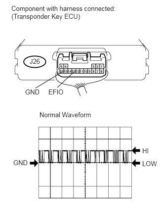
a.
U151971E02
1.208,1.844 1.563,1.51 false 0.75,1.854 1.302,1.521 false 0.625,1.208 0.917,1.417 0.292,0.208 10 false J26 0.24,0.094 2.729,0.458 2.49,0.365 10 false Component with harness connected: (Transponder Key ECU) 0.833,2.333 2.031,2.5 1.198,0.167 10 false Normal Waveform 3,3.365 3.333,3.531 0.333,0.167 10 false LOW 3,3.094 3.208,3.26 0.208,0.167 10 false HI 0.281,3.344 0.615,3.51 0.333,0.167 10 false GND 0.531,1.854 0.938,2.021 0.406,0.167 10 false GND 1.021,1.854 1.427,2.021 0.406,0.167 10 false EFIO

Measure waveform.

Waveform 1 (Reference)
Terminal No. (Symbols) Tool Setting Switch Condition
J26-13 (EFIO) - J26-16 (GND) 10 V/DIV., 100 msec./DIV. Ignition switch ON

OK:

Waveform is output normally (see illustration).


Result
Result Proceed to
Waveform is not output normally A
Waveform is output normally (for 1UR-FE) B
Waveform is output normally (for 3UR-FE) C
Waveform is output normally (for 3UR-FBE) D


A

5.CHECK TRANSPONDER KEY ECU (POWER SOURCE AND BODY GROUND)

B

C

D

5.CHECK TRANSPONDER KEY ECU (POWER SOURCE AND BODY GROUND)
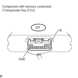
a.
U151859E01
2.553,1.246 2.809,1.392 0.257,0.147 10 +B 0.089,0.199 2.482,0.541 2.393,0.342 10 Component with harness connected: (Transponder Key ECU) 1.546,1.118 1.864,1.300 0.318,0.183 10 J26 2.176,1.969 2.553,1.331 false 0.813,2.522 1.154,2.669 0.341,0.147 10 GND 1.019,2.522 1.315,2.126 false

Measure the voltage according to the value(s) in the table below.

Standard voltage:
Tester Connection Condition Specified Condition
J26-1 (+B) - J26-16 (GND) Always 11 to 14 V


OK

NG

REPAIR OR REPLACE HARNESS OR CONNECTOR