INTERIOR ROOF HEADLINING(for CrewMax) INSTALLATION
CAUTION / NOTICE / HINT
- HINT:
-
A bolt without a torque specification is shown in the standard bolt chart (See page General>SPECIFICATIONS>STANDARD BOLT>SPECIFIED TORQUE FOR STANDARD BOLTS).
PROCEDURE

 63310
1.INSTALL ROOF HEADLINING ASSEMBLY
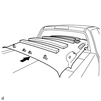
Place the roof headlining assembly into the cabin as shown in the illustration.
- NOTICE:
-
Be careful not to damage the roof headlining assembly when placing it in the cabin.
w/o Sliding Roof:
Attach the 4 clips to install the roof headlining assembly.
w/ Sliding Roof:
Attach the 4 clips and 12 fasteners to install the roof headlining assembly.
Attach the 4 wire harness clamps and connect the connector to the front pillar LH.
w/ EC Mirror:
Connect the connector.
74610A
2.INSTALL ASSIST GRIP SUB-ASSEMBLY
74348
3.INSTALL VISOR HOLDER
74320
4.INSTALL VISOR ASSEMBLY LH
74310
5.INSTALL VISOR ASSEMBLY RH
- HINT:
-
Use the same procedure described for the LH side.
81240
6.INSTALL ROOM LIGHT ASSEMBLY
87834
7.INSTALL INNER REAR VIEW MIRROR STAY HOLDER COVER (w/ EC Mirror)
63650A
8.INSTALL ROOF CONSOLE BOX ASSEMBLY
73034
9.INSTALL REAR SHOULDER BELT ANCHOR PLATE SUB-ASSEMBLY LH
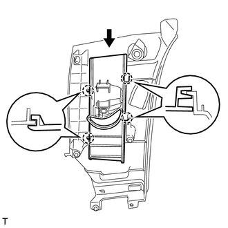
Slide the rear shoulder belt anchor plate sub-assembly LH in the direction shown in the illustration and attach the 4 claws to install it.
73033
10.INSTALL REAR SHOULDER BELT ANCHOR PLATE SUB-ASSEMBLY RH
- HINT:
-
Use the same procedure described for the LH side.
62520P
11.INSTALL FRONT QUARTER TRIM PANEL ASSEMBLY LH
Pass the rear seat outer belt assembly through the hole of the front quarter trim panel assembly LH.
Attach the 4 clips to install the front quarter trim panel assembly LH.
Install the 2 bolts.
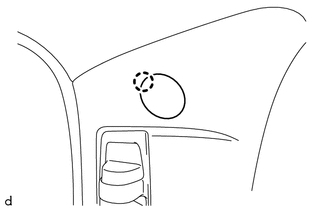
Attach the claw to close the cover.
62510P
12.INSTALL FRONT QUARTER TRIM PANEL ASSEMBLY RH
- HINT:
-
Use the same procedure described for the LH side.
62540
13.INSTALL LOWER QUARTER TRIM PANEL ASSEMBLY LH
Attach the 5 clips to install the lower quarter trim panel assembly LH.
Connect the rear seat outer belt assembly with the bolt.
- Torque:
- 42 N*m (428 kgf*cm, 31 ft.*lbf)
Attach the 2 claws to install the cover.
62530
14.INSTALL LOWER QUARTER TRIM PANEL ASSEMBLY RH
- HINT:
-
Use the same procedure described for the LH side.
86150
15.INSTALL NO. 1 BOX SPEAKER ASSEMBLY (w/ Woofer)
73024
16.INSTALL FRONT SHOULDER BELT ANCHOR PLATE SUB-ASSEMBLY LH
73023
17.INSTALL FRONT SHOULDER BELT ANCHOR PLATE SUB-ASSEMBLY RH
- HINT:
-
Use the same procedure described for the LH side.
62412
18.INSTALL CENTER PILLAR GARNISH LH
62411
19.INSTALL CENTER PILLAR GARNISH RH
- HINT:
-
Use the same procedure described for the LH side.
62414A
20.INSTALL LOWER CENTER PILLAR GARNISH LH
62413A
21.INSTALL LOWER CENTER PILLAR GARNISH RH
- HINT:
-
Use the same procedure described for the LH side.
62212
22.INSTALL FRONT PILLAR GARNISH LH
62211
23.INSTALL FRONT PILLAR GARNISH RH
62332A
24.INSTALL REAR DOOR OPENING TRIM WEATHERSTRIP LH
Install the rear door opening trim weatherstrip LH.
62331A
25.INSTALL REAR DOOR OPENING TRIM WEATHERSTRIP RH
- HINT:
-
Use the same procedure described for the LH side.
62312B
26.INSTALL FRONT DOOR OPENING TRIM WEATHERSTRIP LH
Install the front door opening trim weatherstrip LH.
62311B
27.INSTALL FRONT DOOR OPENING TRIM WEATHERSTRIP RH
- HINT:
-
Use the same procedure described for the LH side.
62112
28.INSTALL COWL SIDE TRIM BOARD LH
62111C
29.INSTALL COWL SIDE TRIM BOARD RH
- HINT:
-
Use the same procedure described for the LH side.
67918B
30.INSTALL REAR DOOR SCUFF PLATE LH
Attach the 8 claws and 2 clips to install the rear door scuff plate LH.
67917B
31.INSTALL REAR DOOR SCUFF PLATE RH
- HINT:
-
Use the same procedure described for the LH side.
67914
32.INSTALL FRONT DOOR SCUFF PLATE LH
Attach the 6 claws and 3 clips to install the front door scuff plate LH.
67913
33.INSTALL FRONT DOOR SCUFF PLATE RH
- HINT:
-
Use the same procedure described for the LH side.
34.INSTALL REAR SEAT ASSEMBLY (for LH Side)
35.INSTALL REAR SEAT ASSEMBLY (for RH Side)
36.INSTALL FRONT SEAT ASSEMBLY (for Center Seat)
37.INSTALL FRONT SEAT ASSEMBLY (for Manual Seat)
38.INSTALL FRONT SEAT ASSEMBLY (for Power Seat)
39.CONNECT CABLE TO NEGATIVE BATTERY TERMINAL
- NOTICE:
-
When disconnecting the cable, some systems need to be initialized after the cable is reconnected (See page General>INTRODUCTION>REPAIR INSTRUCTION>INITIALIZATION).
40.CHECK SRS WARNING LIGHT