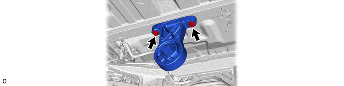
Q510 HYBRID TRANSMISSION / TRANSAXLE REAR TRACTION MOTOR REMOVAL
CAUTION / NOTICE / HINT
| Procedure | Part Name Code | 
|

|

|
|
|---|---|---|---|---|---|
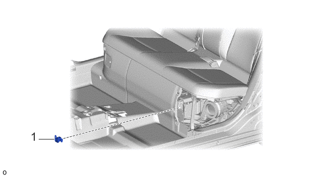
| 1 | SERVICE PLUG GRIP | G3834 | - | - | - |
| Procedure | Part Name Code |
|
|
|
|
|---|---|---|---|---|---|
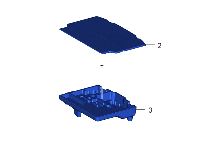
| 2 | DECK BOARD ASSEMBLY | 58410B | - | - | - |
| 3 | REAR DECK FLOOR BOX | 64993 | - | - | - |
| Procedure | Part Name Code |
|
|
|
|
|---|---|---|---|---|---|
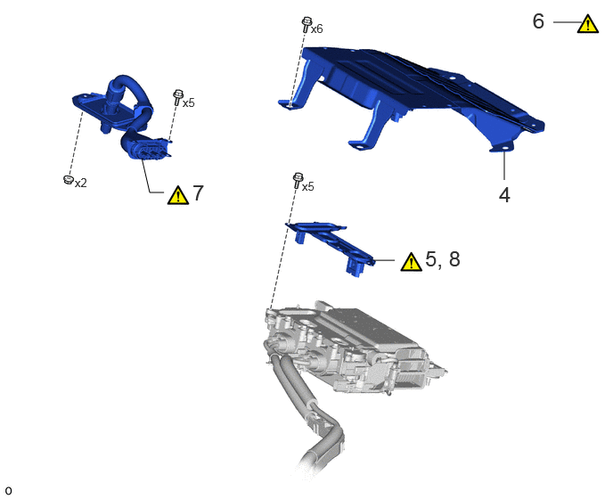
| 4 | HYBRID INVERTER PROTECTOR ASSEMBLY | G92D0 | - | - | - |
| 5 | REMOVE INVERTER TERMINAL COVER | G9223 | ( ) |
- | - |
| 6 | CHECK TERMINAL VOLTAGE | - | ()
|
- | - |
| 7 | REAR TRACTION MOTOR CABLE | G1149 | ()
|
- | - |
| 8 | TEMPORARILY TIGHTEN INVERTER TERMINAL COVER | G9223 | ()
|
- | - |
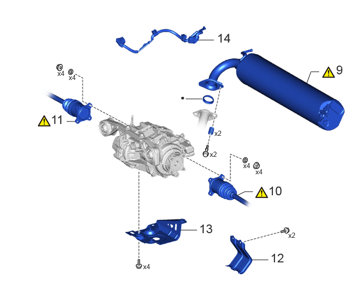
| Procedure | Part Name Code |
|
|
|
|
|---|---|---|---|---|---|
| 9 | TAIL EXHAUST PIPE ASSEMBLY | 17430 | ()
|
- | - |
| 10 | REAR DRIVE SHAFT ASSEMBLY LH | 42340B | ()
|
- | - |
| 11 | REAR DRIVE SHAFT ASSEMBLY RH | 42330 | ()
|
- | - |
| 12 | DIFFERENTIAL SUPPORT PROTECTOR | 52383C | - | - | - |
| 13 | REAR DIFFERENTIAL PROTECTOR | 41171 | - | - | - |
| 14 | NO. 6 FLOOR WIRE | 82169A | - | - | - |
| ● | Non-reusable part | - | - |
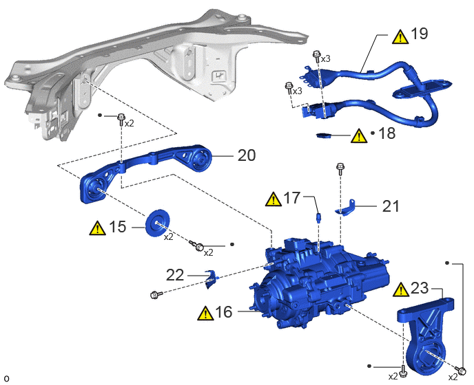
| Procedure | Part Name Code |
|
|
|
|
|---|---|---|---|---|---|
| 15 | UPPER DIFFERENTIAL MOUNT STOPPER | 41653D | ()
|
- | - |
| 16 | REAR TRACTION MOTOR WITH TRANSAXLE ASSEMBLY | G1050 | ()
|
- | - |
| 17 | REAR TRACTION MOTOR BREATHER PLUG | 30900T | ()
|
- | - |
| 18 | MOTOR CABLE TERMINAL CAP | G114D | ()
|
- | - |
| 19 | REAR TRACTION MOTOR CABLE | G1149 | ()
|
- | - |
| 20 | FRONT DIFFERENTIAL SUPPORT ASSEMBLY | 52380F | - | - | - |
| 21 | MOTOR CABLE BRACKET | G1143 | - | - | - |
| 22 | WIRE HARNESS CLAMP BRACKET | - | - | - | - |
| 23 | REAR DIFFERENTIAL SUPPORT ASSEMBLY | 52390B | ()
|
- | - |
| ● | Non-reusable part | - | - |
CAUTION / NOTICE / HINT
The necessary procedures (adjustment, calibration, initialization, or registration) that must be performed after parts are removed and installed, or replaced during the rear traction motor with transaxle assembly removal/installation are shown below.
| Replaced Part or Performed Procedure | Necessary Procedure | Effect/Inoperative Function when Necessary Procedure not Performed | Link |
|---|---|---|---|
| Auxiliary battery terminal is disconnected/reconnected | Memorize steering angle neutral point | Parking assist monitor system | ()
|
| Panoramic view monitor system | ()
|
||
| Gas leaks from exhaust system | Inspection after repair | ·
Poor idle, etc. ·
Engine start function, etc. |
()
|
- CAUTION:
-
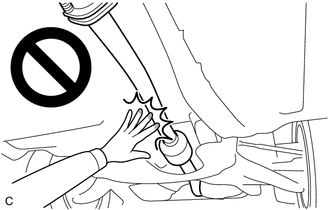
-
To prevent burns, do not touch the engine, exhaust pipe or other high temperature components while the engine is hot.
- HINT:
-
When the cable is disconnected / reconnected to the auxiliary battery terminal, systems temporarily stop operating. However, each system has a function that completes learning the first time the system is used.
- ·
Learning completes when vehicle is driven
Effect/Inoperative Function When Necessary Procedures are not Performed Necessary Procedures Link Lane tracing assist system Drive the vehicle straight ahead at 35 km/h (22 mph) or more for 5 second or more. ( )
Pre-collision system Parking support brake system
·Learning completes when vehicle is operated normally
Effect/Inoperative Function When Necessary Procedures are not Performed Necessary Procedures Link Power door lock control system
·Back door opener
Perform door unlock operation with door control switch or electrical key transmitter sub-assembly switch. ( )
Power back door system Fully close the back door by hand.
- HINT:
-
Initialization is not necessary if the above procedures are performed while the back door is closed.
( )
Air conditioning system After the ignition switch is turned to ON, the servo motor standard position is recognized. -
PROCEDURE

 G3834
1.REMOVE SERVICE PLUG GRIP
58410B
2.REMOVE DECK BOARD ASSEMBLY
64993
3.REMOVE REAR DECK FLOOR BOX
G92D0
4.REMOVE HYBRID INVERTER PROTECTOR ASSEMBLY
G9223
5.REMOVE INVERTER TERMINAL COVER
|
|
Click here()
|
6.CHECK TERMINAL VOLTAGE
G1149
7.DISCONNECT REAR TRACTION MOTOR CABLE
|
|
Click here()
|
G9223
8.TEMPORARILY INSTALL INVERTER TERMINAL COVER
|
|
Click here()
|
17430
9.REMOVE TAIL EXHAUST PIPE ASSEMBLY
|
|
Click here()
|
42340B
10.DISCONNECT REAR DRIVE SHAFT ASSEMBLY LH
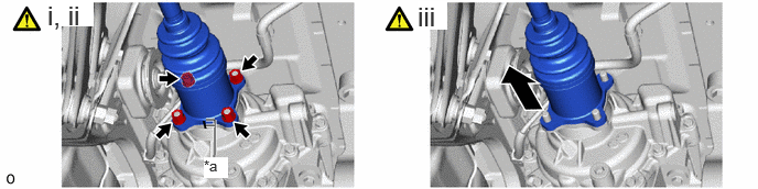
| *a | Matchmark | - | - |
Put matchmarks on the rear drive shaft assembly LH and differential side gear shaft sub-assembly.
Remove the 4 nuts and 4 washers.
Push the rear drive shaft inboard joint assembly LH toward the outside of the vehicle and remove the rear drive shaft assembly LH from the differential side gear shaft sub-assembly.
- NOTICE:
- ·
Do not damage the rear drive shaft inboard joint boot.
·Do not drop the rear drive shaft assembly LH.
42330
11.DISCONNECT REAR DRIVE SHAFT ASSEMBLY RH
Perform the same procedure as for the LH side.
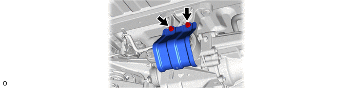
52383C
12.REMOVE DIFFERENTIAL SUPPORT PROTECTOR
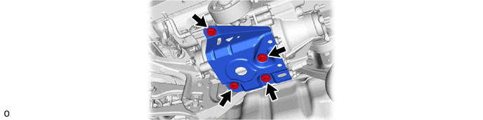
41171
13.REMOVE REAR DIFFERENTIAL PROTECTOR
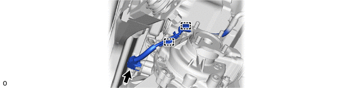
82169A
14.SEPARATE NO. 6 FLOOR WIRE
41653D
15.REMOVE UPPER DIFFERENTIAL MOUNT STOPPER
|
|
|
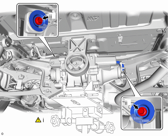
Support the rear traction motor with transaxle assembly with a transmission jack.
Remove the 2 bolts and 2 upper differential mount stoppers.
G1050
16.REMOVE REAR TRACTION MOTOR WITH TRANSAXLE ASSEMBLY
|
|
|
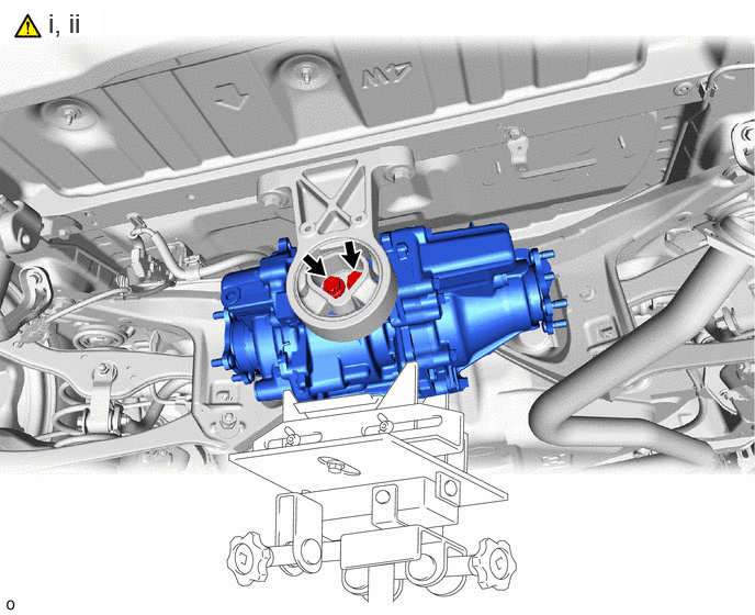
Remove the 2 bolts.
Operate the transmission jack and remove the rear traction motor with transaxle assembly from the rear differential support assembly.
30900T
17.REMOVE REAR TRACTION MOTOR BREATHER PLUG
|
|
|
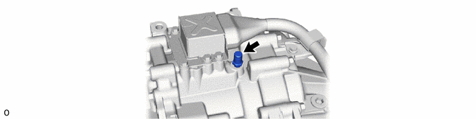
G114D
18.REMOVE MOTOR CABLE TERMINAL CAP
|
|
Click here()
|
G1149
19.REMOVE REAR TRACTION MOTOR CABLE
|
|
Click here()
|
52380F
20.REMOVE FRONT DIFFERENTIAL SUPPORT ASSEMBLY
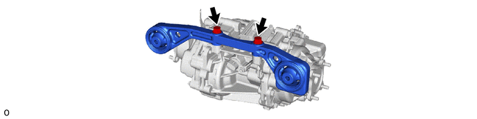
G1143
21.REMOVE MOTOR CABLE BRACKET
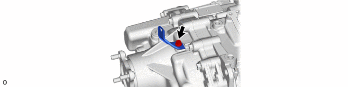
22.REMOVE WIRE HARNESS CLAMP BRACKET
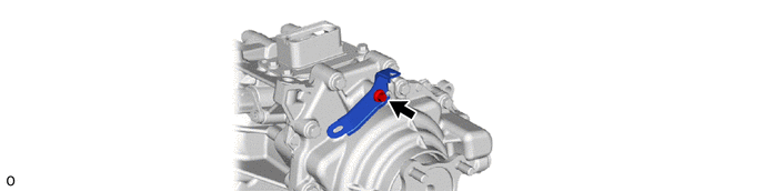
52390B
23.REMOVE REAR DIFFERENTIAL SUPPORT ASSEMBLY
|
|
|