STEERING COLUMN STEERING COLUMN ASSEMBLY INSTALLATION
CAUTION / NOTICE / HINT
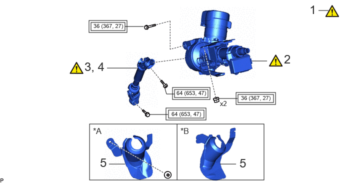
| Procedure | Part Name Code | 
|

|

|
|
|---|---|---|---|---|---|
| 1 | ALIGN FRONT WHEELS FACING STRAIGHT AHEAD | - | ( ) |
- | - |
| 2 | STEERING COLUMN ASSEMBLY | - | ()
|
- | - |
| 3 | INSTALL NO. 2 STEERING INTERMEDIATE SHAFT ASSEMBLY | 45260 | ()
|
- | - |
| 4 | CONNECT NO. 2 STEERING INTERMEDIATE SHAFT ASSEMBLY | 45260 | ()
|
- | - |
| 5 | COLUMN HOLE COVER SILENCER SHEET | 45259A | - | - | - |
| *A | for LHD | *B | for RHD |

|
Tightening torque for "Major areas involving basic vehicle performance such as moving/turning/stopping": N*m (kgf*cm, ft.*lbf) | - | - |
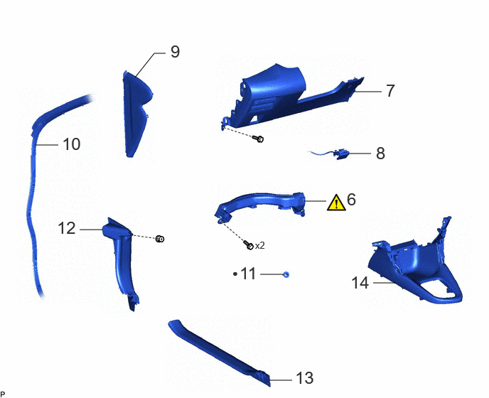
| Procedure | Part Name Code |
|
|
|
|
|---|---|---|---|---|---|
| 6 | NO. 1 AIR DUCT | 87211 | ()
|
- | - |
| 7 | LOWER INSTRUMENT PANEL FINISH PANEL ASSEMBLY | 55480D | - | - | - |
| 8 | HOOD LOCK CONTROL LEVER SUB-ASSEMBLY | 53601 | - | - | - |
| 9 | NO. 1 INSTRUMENT SIDE PANEL | 55317E | - | - | - |
| 10 | FRONT DOOR OPENING TRIM WEATHERSTRIP LH | 62312B | - | - | - |
| 11 | STOP LIGHT SWITCH MOUNTING ADJUSTER | 84345 | - | - | - |
| 12 | COWL SIDE TRIM BOARD LH | 62112 | - | - | - |
| 13 | FRONT DOOR SCUFF PLATE LH | 67914B | - | - | - |
| 14 | CONSOLE BOX ASSEMBLY | 58810J | - | - | - |
| ● | Non-reusable part | - | - |
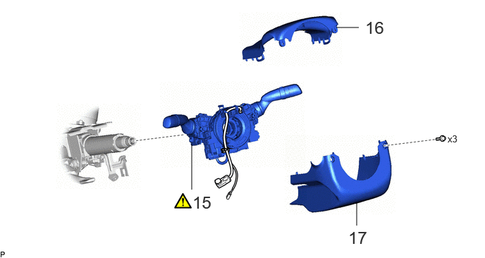
| Procedure | Part Name Code |
|
|
|
|
|---|---|---|---|---|---|
| 15 | TURN SIGNAL SWITCH ASSEMBLY WITH SPIRAL CABLE SUB-ASSEMBLY | - | ()
|
- | - |
| 16 | UPPER STEERING COLUMN COVER | - | - | - | - |
| 17 | LOWER STEERING COLUMN COVER | - | - | - | - |
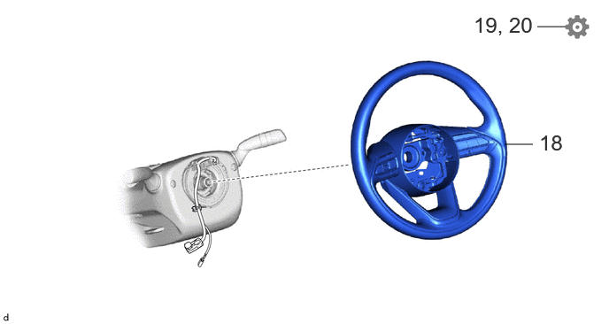
| Procedure | Part Name Code |
|
|
|
|
|---|---|---|---|---|---|
| 18 | STEERING WHEEL ASSEMBLY | 45100 | - | - | - |
| 19 | PERFORM POWER STEERING ECU INITIAL SETTING | - | - | - | ()
|
| 20 | PERFORM INITIALIZATION AND CALIBRATION | - | - | - | ()
|
CAUTION / NOTICE / HINT
- HINT:
- ·
Use the same procedure as for the LHD and RHD vehicles.
·The procedure listed below is for the LHD vehicles.
PROCEDURE

 1.ALIGN FRONT WHEELS FACING STRAIGHT AHEAD
|
|
Click here()
|
2.INSTALL STEERING COLUMN ASSEMBLY
|
|
|
- Torque:
- 36 N*m (367 kgf*cm, 27 ft.*lbf)
45260
3.INSTALL NO. 2 STEERING INTERMEDIATE SHAFT ASSEMBLY

| *a | Matchmark | - | - |

|
Install in this direction | - | - |
Align the matchmarks on the No. 2 steering intermediate shaft assembly and steering column assembly.
Install the No. 2 steering intermediate shaft assembly to the steering column assembly.
Install the bolt.
- Torque:
- 64 N*m (653 kgf*cm, 47 ft.*lbf)
45260
4.CONNECT NO. 2 STEERING INTERMEDIATE SHAFT ASSEMBLY

| *a | Matchmark | - | - |
|
|
Connect in this direction | - | - |
Align the matchmarks on the No. 2 steering intermediate shaft assembly and steering gear assembly.
Connect the No. 2 steering intermediate shaft assembly to the steering gear assembly.
Install the bolt.
- Torque:
- 64 N*m (653 kgf*cm, 47 ft.*lbf)
45259A
5.INSTALL COLUMN HOLE COVER SILENCER SHEET
87211
6.INSTALL NO. 1 AIR DUCT
|
|
Click here()
|
55480D
7.INSTALL LOWER INSTRUMENT PANEL FINISH PANEL ASSEMBLY
53601
8.CONNECT HOOD LOCK CONTROL LEVER SUB-ASSEMBLY
55317E
9.INSTALL NO. 1 INSTRUMENT SIDE PANEL
62312B
10.INSTALL FRONT DOOR OPENING TRIM WEATHERSTRIP LH
84345
11.INSTALL STOP LIGHT SWITCH MOUNTING ADJUSTER
62112
12.INSTALL COWL SIDE TRIM BOARD LH
67914B
13.INSTALL FRONT DOOR SCUFF PLATE LH
58810J
14.INSTALL CONSOLE BOX ASSEMBLY
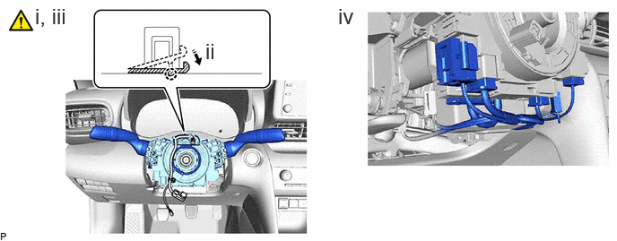
15.INSTALL TURN SIGNAL SWITCH ASSEMBLY WITH SPIRAL CABLE SUB-ASSEMBLY
|
|
|
|
|
Install in this direction | - | - |
Using pliers, expand the clamp.
While holding the clamp expanded, install the turn signal switch assembly with spiral cable sub-assembly to the steering column assembly and engage the claw.
Return the clamp to its original position.
Connect each connector.
- HINT:
-
As the illustration shown is an example, the actual details may differ.
16.INSTALL UPPER STEERING COLUMN COVER
17.INSTALL LOWER STEERING COLUMN COVER
45100
18.INSTALL STEERING WHEEL ASSEMBLY
19. PERFORM POWER STEERING ECU INITIAL SETTING
20.PERFORM INITIALIZATION AND CALIBRATION
| Parking Assist Monitor System | for Initialization:()
for Calibration:( )
|
| Panoramic View Monitor System (w/ Advanced Park) | ()
|
| Panoramic View Monitor System (w/o Advanced Park) | for Initialization:()
for Calibration:( )
|