BRAKE SYSTEM (OTHER) BRAKE BOOSTER(for LHD) INSTALLATION
PROCEDURE

 44610
1.INSTALL BRAKE BOOSTER ASSEMBLY
Install a new gasket onto the brake booster assembly.
Temporarily install the brake booster assembly with the 4 nuts.
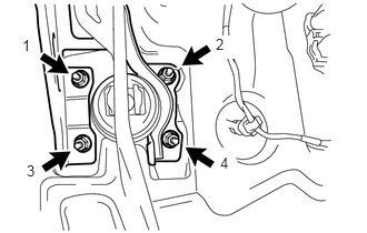
Tighten the 4 nuts in the order shown in the illustration.
- Torque:
- 9.0 N*m (92 kgf*cm, 80 in.*lbf)
Connect the vacuum hose to the vacuum check valve with the clip.
45260
2.INSTALL NO. 2 STEERING INTERMEDIATE SHAFT ASSEMBLY
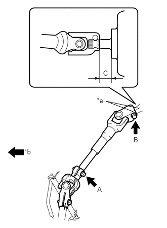
Align the matchmarks on the No. 2 steering intermediate shaft assembly and the steering column assembly and provisionally install them with the bolt.
| *a | Matchmark |
| *b | Front of the Vehicle |
Tighten the bolt B while aligning the No. 2 steering intermediate shaft assembly with the position C as shown in the illustration.
- Standard C:
18.5 to 19.7 mm
- Torque:
- 35 N*m (360 kgf*cm, 26 ft.*lbf)
Tighten bolt A.
- Torque:
- 35 N*m (360 kgf*cm, 26 ft.*lbf)
47264D
3.INSTALL BRAKE MASTER CYLINDER PUSH ROD CLEVIS
55711
4.INSTALL OUTER COWL TOP PANEL
Install the outer cowl top panel with the 8 bolts.
- Torque:
- 7.0 N*m (71 kgf*cm, 62 in.*lbf)
Engage the 2 clamps and install the wire harness.
55722C
5.INSTALL INNER COWL TOP TO COWL BRACE
Install the cowl top to cowl brace with the 2 bolts.
- Torque:
- 7.0 N*m (71 kgf*cm, 62 in.*lbf)
55815E
6.INSTALL FRONT NO. 1 VENTILATOR SEAL
Engage the clip and install the front No. 1 ventilator seal.
55735D
7.INSTALL FRONT AIR SHUTTER SEAL RH
- HINT:
-
Use the same procedure for the RH and LH sides.
47150
8.INSTALL PROPORTIONING VALVE ASSEMBLY (w/o ABS)
44510
9.INSTALL BRAKE ACTUATOR ASSEMBLY (w/ ABS)
47201
10.INSTALL BRAKE MASTER CYLINDER SUB-ASSEMBLY
85110
11.INSTALL WINDSHIELD WIPER MOTOR ASSEMBLY
12.INSPECT AND ADJUST BRAKE PEDAL HEIGHT
55432B
13.INSTALL LOWER INSTRUMENT PANEL FINISH PANEL
for LHD:
Engage the 5 claws and 2 clips and install the instrument panel finish panel.
for RHD:
Engage the 6 claws and 2 clips and install the instrument panel finish panel.
55433B
14.INSTALL LOWER NO. 2 INSTRUMENT PANEL FINISH PANEL
Engage the 2 claws and 5 clips and install the instrument panel finish panel.
55606
15.INSTALL NO. 1 INSTRUMENT PANEL UNDER COVER SUB-ASSEMBLY