Home › Audio / Visual / Telematics › AUDIO / VIDEO › AUDIO AND VISUAL SYSTEM
RM19S0E _56 Audio / Visual / Telematics _051483 AUDIO / VIDEO _0248261 AUDIO AND VISUAL SYSTEM J

AUDIO / VIDEO  AUDIO AND VISUAL SYSTEM  Speaker Circuit  


DESCRIPTION

If there is a short in a speaker circuit, the radio receiver assembly detects it and stops output to the speakers.

Thus sound cannot be heard from the speakers even if there is no malfunction in the radio receiver assembly or speakers.

If a short is detected in a speaker circuit, no sound can be heard from the speakers.

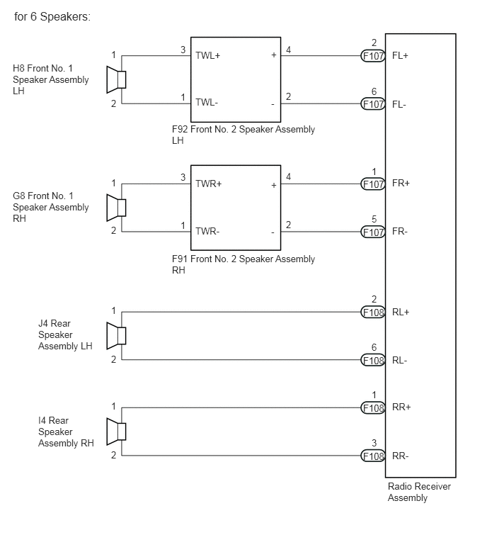
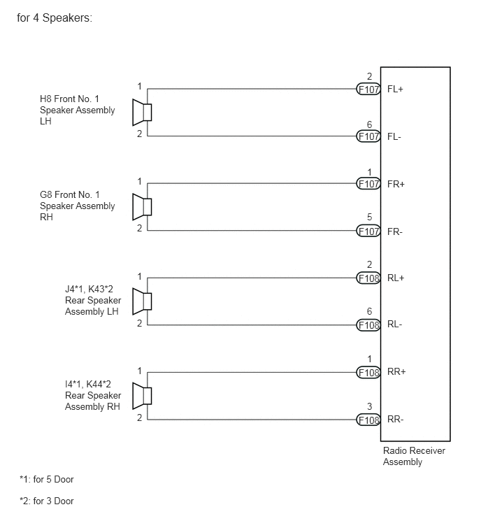
WIRING DIAGRAM
E231978E02
0.594,2.813 1.865,3.74 1.271,0.927 10 false G8 Front No. 1 Speaker Assembly RH 0.969,5.635 1.854,6.76 0.885,1.125 10 false I4*1, K44*2 Rear Speaker Assembly RH 0.969,4.219 1.906,5.427 0.938,1.208 10 false J4*1, K43*2 Rear Speaker Assembly LH 0.594,1.385 1.896,2.313 1.302,0.927 10 false H8 Front No. 1 Speaker Assembly LH 5.708,6.625 6.708,7.333 1,0.708 10 false Radio Receiver Assembly 5.771,6.156 6.052,6.313 0.281,0.156 10 false RR- 5.771,5.448 6.073,5.604 0.302,0.156 10 false RR+ 5.771,4.74 6.052,4.896 0.281,0.156 10 false RL- 5.771,4.052 6.052,4.208 0.281,0.156 10 false RL+ 5.771,3.365 6.052,3.521 0.281,0.156 10 false FR- 5.771,2.656 6.052,2.813 0.281,0.156 10 false FR+ 5.771,1.948 6.052,2.104 0.281,0.156 10 false FL- 5.771,1.24 6.052,1.396 0.281,0.156 10 false FL+ 5.344,4.76 5.688,4.917 0.344,0.156 10 false F108 5.469,4.552 5.646,4.74 0.177,0.188 10 false 6 5.344,4.063 5.688,4.219 0.344,0.156 10 false F108 5.469,3.854 5.646,4.042 0.177,0.188 10 false 2 5.344,6.177 5.688,6.333 0.344,0.156 10 false F108 5.469,5.969 5.646,6.156 0.177,0.188 10 false 3 5.344,5.469 5.688,5.625 0.344,0.156 10 false F108 5.469,5.26 5.646,5.448 0.177,0.188 10 false 1 5.344,3.365 5.688,3.521 0.344,0.156 10 false F107 5.469,3.146 5.646,3.333 0.177,0.188 10 false 5 5.344,2.656 5.688,2.813 0.344,0.156 10 false F107 5.469,2.479 5.646,2.667 0.177,0.188 10 false 1 5.344,1.948 5.688,2.104 0.344,0.156 10 false F107 5.469,1.771 5.646,1.958 0.177,0.188 10 false 6 5.344,1.25 5.688,1.406 0.344,0.156 10 false F107 5.469,1.052 5.646,1.24 0.177,0.188 10 false 2 2.042,4.729 2.219,4.917 0.177,0.188 10 false 2 2.042,4.031 2.219,4.219 0.177,0.188 10 false 1 2.042,3.313 2.219,3.5 0.177,0.188 10 false 2 2.042,2.615 2.219,2.802 0.177,0.188 10 false 1 2.042,1.906 2.219,2.094 0.177,0.188 10 false 2 2.042,1.198 2.219,1.385 0.177,0.188 10 false 1 2.042,6.135 2.219,6.323 0.177,0.188 10 false 2 2.042,5.438 2.219,5.625 0.177,0.188 10 false 1 0.292,7.375 2.052,7.719 1.76,0.344 10 false *2: for 3 Door 0.292,7.052 1.917,7.365 1.625,0.313 10 false *1: for 5 Door 0.25,0.156 1.531,0.51 1.281,0.354 12 false for 4 Speakers:

E231979E03
2.531,3.719 4.698,4.25 2.167,0.531 10 false F91 Front No. 2 Speaker Assembly RH 0.188,2.792 1.5,3.781 1.313,0.99 10 false G8 Front No. 1 Speaker Assembly RH 2.531,1.813 4.698,2.344 2.167,0.531 10 false F92 Front No. 2 Speaker Assembly LH 0.563,6.094 1.49,7.125 0.927,1.031 10 false I4 Rear Speaker Assembly RH 0.563,4.667 1.479,5.74 0.917,1.073 10 false J4 Rear Speaker Assembly LH 0.188,0.917 1.458,1.875 1.271,0.958 10 false H8 Front No. 1 Speaker Assembly LH 5.708,7.063 6.719,7.75 1.01,0.688 10 false Radio Receiver Assembly 5.771,6.615 6.052,6.771 0.281,0.156 10 false RR- 5.771,5.896 6.073,6.052 0.302,0.156 10 false RR+ 5.771,5.208 6.052,5.365 0.281,0.156 10 false RL- 5.771,4.5 6.052,4.656 0.281,0.156 10 false RL+ 2.875,3.313 3.302,3.5 0.427,0.188 10 false TWR- 2.875,2.615 3.302,2.802 0.427,0.188 10 false TWR+ 3.99,3.323 4.167,3.51 0.177,0.188 10 false - 3.99,2.635 4.167,2.823 0.177,0.188 10 false + 3.99,1.438 4.167,1.625 0.177,0.188 10 false - 3.99,0.719 4.167,0.906 0.177,0.188 10 false + 2.875,1.417 3.302,1.604 0.427,0.188 10 false TWL- 2.875,0.729 3.302,0.917 0.427,0.188 10 false TWL+ 5.771,3.313 6.052,3.469 0.281,0.156 10 false FR- 5.771,2.604 6.052,2.76 0.281,0.156 10 false FR+ 5.771,1.448 6.052,1.604 0.281,0.156 10 false FL- 5.771,0.729 6.052,0.885 0.281,0.156 10 false FL+ 5.344,5.219 5.688,5.375 0.344,0.156 10 false F108 5.469,5.021 5.646,5.208 0.177,0.188 10 false 6 5.344,4.51 5.688,4.667 0.344,0.156 10 false F108 5.469,4.313 5.646,4.5 0.177,0.188 10 false 2 5.344,6.625 5.688,6.781 0.344,0.156 10 false F108 5.469,6.427 5.646,6.615 0.177,0.188 10 false 3 5.344,5.917 5.688,6.073 0.344,0.156 10 false F108 5.469,5.719 5.646,5.906 0.177,0.188 10 false 1 5.344,3.333 5.688,3.49 0.344,0.156 10 false F107 5.469,3.135 5.646,3.323 0.177,0.188 10 false 5 5.344,2.625 5.688,2.781 0.344,0.156 10 false F107 5.469,2.438 5.646,2.625 0.177,0.188 10 false 1 5.344,1.448 5.688,1.604 0.344,0.156 10 false F107 5.469,1.26 5.646,1.448 0.177,0.188 10 false 6 5.344,0.74 5.688,0.896 0.344,0.156 10 false F107 5.469,0.542 5.646,0.729 0.177,0.188 10 false 2 1.635,5.198 1.813,5.385 0.177,0.188 10 false 2 1.635,4.479 1.813,4.667 0.177,0.188 10 false 1 1.635,3.302 1.813,3.49 0.177,0.188 10 false 2 1.635,2.604 1.813,2.792 0.177,0.188 10 false 1 1.635,1.438 1.813,1.625 0.177,0.188 10 false 2 1.635,0.719 1.813,0.906 0.177,0.188 10 false 1 1.635,6.604 1.813,6.792 0.177,0.188 10 false 2 1.635,5.885 1.813,6.073 0.177,0.188 10 false 1 4.208,3.219 4.385,3.406 0.177,0.188 10 false 2 4.208,2.51 4.385,2.698 0.177,0.188 10 false 4 2.656,3.229 2.833,3.417 0.177,0.188 10 false 1 2.656,2.521 2.833,2.708 0.177,0.188 10 false 3 4.208,1.333 4.385,1.521 0.177,0.188 10 false 2 4.208,0.646 4.385,0.833 0.177,0.188 10 false 4 2.656,1.344 2.833,1.531 0.177,0.188 10 false 1 2.656,0.646 2.833,0.833 0.177,0.188 10 false 3 0.208,0.135 1.49,0.49 1.281,0.354 12 false for 6 Speakers:

PROCEDURE

1.CONFIRM MODEL
Result
Result Proceed to
for 4 Speakers A
for 6 Speakers B


A

2.CHECK HARNESS AND CONNECTOR

B

3.CHECK HARNESS AND CONNECTOR
2.CHECK HARNESS AND CONNECTOR
a.

Disconnect the F107 and F108 radio receiver assembly connectors.


b.

Disconnect the H8 and G8 front No. 1 speaker assembly connectors.


c.

Disconnect the J4*1 and I4*1 or K43*2 and K44*2 rear speaker assembly connectors.

*1: for 5 Door

*2: for 3 Door


d.

Measure the resistance between each of the radio receiver assembly and the front No. 1 speaker assembly to check for an open circuit in the wire harness.

Standard Resistance:
Tester Connection Condition Specified Condition
F107-2 (FL+) - H8-1 Always Below 1 Ω
F107-6 (FL-) - H8-2 Always Below 1 Ω
F107-1 (FR+) - G8-1 Always Below 1 Ω
F107-5 (FR-) - G8-2 Always Below 1 Ω


e.

Measure the resistance between each of the radio receiver assembly and the rear speaker assembly to check for an open circuit in the wire harness.

Standard Resistance:
for 5 Door
Tester Connection Condition Specified Condition
F108-2 (RL+) - J4-1 Always Below 1 Ω
F108-6 (RL-) - J4-2 Always Below 1 Ω
F108-1 (RR+) - I4-1 Always Below 1 Ω
F108-3 (RR-) - I4-2 Always Below 1 Ω

for 3 Door
Tester Connection Condition Specified Condition
F108-2 (RL+) - K43-1 Always Below 1 Ω
F108-6 (RL-) - K43-2 Always Below 1 Ω
F108-1 (RR+) - K44-1 Always Below 1 Ω
F108-3 (RR-) - K44-2 Always Below 1 Ω


f.

Measure the resistance between each speaker assembly and body ground to check for a short circuit in the wire harness.

Standard Resistance:
Tester Connection Condition Specified Condition
H8-1 - Body ground Always 10 kΩ or higher
H8-2 - Body ground Always 10 kΩ or higher
G8-1 - Body ground Always 10 kΩ or higher
G8-2 - Body ground Always 10 kΩ or higher
J4-1 - Body ground*1 Always 10 kΩ or higher
J4-2 - Body ground*1 Always 10 kΩ or higher
I4-1 - Body ground*1 Always 10 kΩ or higher
I4-2 - Body ground*1 Always 10 kΩ or higher
K43-1 - Body ground*2 Always 10 kΩ or higher
K43-2 - Body ground*2 Always 10 kΩ or higher
K44-1 - Body ground*2 Always 10 kΩ or higher
K44-2 - Body ground*2 Always 10 kΩ or higher


*1: for 5 Door

*2: for 3 Door


Result
Result Proceed to
NG A
OK B


A

REPAIR OR REPLACE HARNESS OR CONNECTOR

B

5.INSPECT FRONT NO. 1 SPEAKER ASSEMBLY
3.CHECK HARNESS AND CONNECTOR
a.

Disconnect the F107 and F108 radio receiver assembly connectors.


b.

Disconnect the H8 and G8 front No. 1 speaker assembly connectors.


c.

Disconnect the F92 and F91 front No. 2 speaker assembly connectors.


d.

Disconnect the J4 and I4 rear speaker assembly connectors.


e.

Measure the resistance between each of the radio receiver assembly and the front No. 2 speaker assembly to check for an open circuit in the wire harness.

Standard Resistance:
Tester Connection Condition Specified Condition
F107-2 (FL+) - F92-4 (+) Always Below 1 Ω
F107-6 (FL-) - F92-2 (-) Always Below 1 Ω
F107-1 (FR+) - F91-4 (+) Always Below 1 Ω
F107-5 (FR-) - F91-2 (-) Always Below 1 Ω


f.

Measure the resistance between each of the front No. 2 speaker assembly and front No. 1 speaker assembly to check for an open circuit in the wire harness.

Standard Resistance:
Tester Connection Condition Specified Condition
F92-3 (TWL+) - H8-1 Always Below 1 Ω
F92-1 (TWL-) - H8-2 Always Below 1 Ω
F91-3 (TWR+) - G8-1 Always Below 1 Ω
F91-1 (TWR-) - G8-2 Always Below 1 Ω


g.

Measure the resistance between each of the radio receiver assembly and the rear speaker assembly to check for an open circuit in the wire harness.

Standard Resistance:
Tester Connection Condition Specified Condition
F108-2 (RL+) - J4-1 Always Below 1 Ω
F108-6 (RL-) - J4-2 Always Below 1 Ω
F108-1 (RR+) - I4-1 Always Below 1 Ω
F108-3 (RR-) - I4-2 Always Below 1 Ω


h.

Measure the resistance between each speaker assembly and body ground to check for a short circuit in the wire harness.

Standard Resistance:
Tester Connection Condition Specified Condition
H8-1 - Body ground Always 10 kΩ or higher
H8-2 - Body ground Always 10 kΩ or higher
G8-1 - Body ground Always 10 kΩ or higher
G8-2 - Body ground Always 10 kΩ or higher
F92-4 (+) - Body ground Always 10 kΩ or higher
F92-2 (-) - Body ground Always 10 kΩ or higher
F91-4 (+) - Body ground Always 10 kΩ or higher
F91-2 (-) - Body ground Always 10 kΩ or higher
J4-1 - Body ground Always 10 kΩ or higher
J4-2 - Body ground Always 10 kΩ or higher
I4-1 - Body ground Always 10 kΩ or higher
I4-2 - Body ground Always 10 kΩ or higher


OK

4.INSPECT FRONT NO. 2 SPEAKER ASSEMBLY

NG

REPAIR OR REPLACE HARNESS OR CONNECTOR

4.INSPECT FRONT NO. 2 SPEAKER ASSEMBLY
a.

Check that the malfunction disappears when another speaker in good condition is installed.

OK:

Malfunction disappears.


HINT:
·

Connect all the connectors to the front No. 2 speakers.

·

If there is a possibility that either the right or left front speaker is defective, inspect by interchanging the right one with the left one.

·

Perform the above inspection on both LH and RH sides.


OK

5.INSPECT FRONT NO. 1 SPEAKER ASSEMBLY

NG

REPLACE FRONT NO. 2 SPEAKER ASSEMBLY

5.INSPECT FRONT NO. 1 SPEAKER ASSEMBLY
a.

Inspect the front No. 1 speaker assembly (See page Audio / Visual / Telematics>AUDIO / VIDEO>FRONT DOOR SPEAKER>INSPECTION).

HINT:

The speaker should not be removed to check resistance.


OK

6.INSPECT REAR SPEAKER ASSEMBLY

NG

REPLACE FRONT NO. 1 SPEAKER ASSEMBLY

6.INSPECT REAR SPEAKER ASSEMBLY
a.

Inspect the rear speaker assembly.


HINT:

The speaker should not be removed to check resistance.


Result
Result Proceed to
OK A
NG (for 5 Door) B
NG (for 3 Door) C


A

PROCEED TO NEXT SUSPECTED AREA SHOWN IN PROBLEM SYMPTOMS TABLE

B

C