AXLE AND DIFFERENTIAL STEERING KNUCKLE INSTALLATION
CAUTION / NOTICE / HINT
- HINT:
- ·
Use the same procedure for the RH side and LH side.
·The procedure listed below is for the LH side.
PROCEDURE

 43502C
1.INSTALL FRONT AXLE HUB SUB-ASSEMBLY
Hold the steering knuckle in a vise between aluminum plates.
- NOTICE:
-
When using a vise, do not overtighten it.
Install the front disc brake dust cover and front axle hub sub-assembly to the steering knuckle with the 3 bolts.
- Torque:
- 145 N*m (1479 kgf*cm, 107 ft.*lbf)
- NOTICE:
- ·
Do not place the front speed sensor side so that it is facing downward, and do not allow the front speed sensor side to become damaged or contact foreign matter (w/ ABS).
·Do not drop the front axle hub sub-assembly.
2.INSTALL FRONT AXLE ASSEMBLY
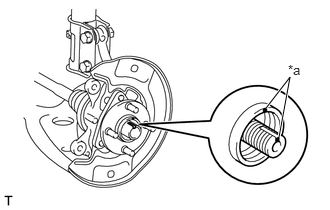
| *a | Matchmark |
Align the matchmarks on the front drive shaft assembly and front axle hub sub-assembly, and install the front drive shaft assembly to the front axle assembly.
- NOTICE:
-
Be careful not to damage the thread portion of the front drive shaft assembly.
Install the front axle assembly to the front shock absorber assembly with the 2 bolts and 2 nuts.
- Torque:
- 164 N*m (1672 kgf*cm, 121 ft.*lbf)
- HINT:
-
Keep the bolt from rotating while turning the nut.
48069
3.INSTALL FRONT LOWER NO. 1 SUSPENSION ARM SUB-ASSEMBLY
Install the front lower No. 1 suspension arm sub-assembly to the front axle assembly with the castle nut.
Using a 19 mm ball joint lock nut wrench, fully tighten the castle nut.
- Torque:
- 98 N*m (999 kgf*cm, 72 ft.*lbf)
- NOTICE:
- ·
Use the formula to calculate special torque values for situations where a ball joint lock nut wrench is combined with a torque wrench.
Click hereGeneral>INTRODUCTION>REPAIR INSTRUCTION>PRECAUTION
·If the holes for the cotter pin are not aligned, tighten the castle nut by a further turn of up to 60°.
·Do not allow any oil or grease to contact the threaded or tapered portions.
·Do not damage the front disc brake dust cover.
Install a new clip.
45047
4.INSTALL TIE ROD END SUB-ASSEMBLY
Install the tie rod end sub-assembly to the front axle assembly with the castle nut.
- Torque:
- 49 N*m (500 kgf*cm, 36 ft.*lbf)
- NOTICE:
- ·
If the holes for the clip are not aligned, tighten the castle nut by a further turn of up to 60°.
·Do not damage the front disc brake dust cover.
Install a new cotter pin.
48819A
5.INSTALL FRONT STABILIZER BOLT
43512
6.INSTALL FRONT DISC
7.INSTALL FRONT DISC BRAKE CALIPER ASSEMBLY
43502H
8.TEMPORARILY INSTALL FRONT AXLE SHAFT NUT
9.SEPARATE FRONT DISC BRAKE CALIPER ASSEMBLY
43512
10.REMOVE FRONT DISC
Click hereBrake>BRAKE (FRONT)>FRONT BRAKE>REMOVAL
11.INSPECT FRONT AXLE HUB BEARING LOOSENESS
12.INSPECT FRONT AXLE HUB RUNOUT
43512
13.INSTALL FRONT DISC
14.INSTALL FRONT DISC BRAKE CALIPER ASSEMBLY
43502H
15.INSTALL FRONT AXLE SHAFT NUT
16.INSTALL FRONT SPEED SENSOR WIRE (w/ ABS)
47313A
17.INSTALL FRONT FLEXIBLE HOSE (w/o ABS)
53876A
18.INSTALL FRONT FENDER LINER (w/ ABS)
19.INSTALL FRONT WHEEL
- Torque:
- 103 N*m (1050 kgf*cm, 76 ft.*lbf)
20.INSPECT AND ADJUST FRONT WHEEL ALIGNMENT
21.CHECK FOR SPEED SENSOR SIGNAL (w/ ABS)