C50 MANUAL TRANSMISSION / TRANSAXLE MANUAL TRANSAXLE ASSEMBLY(for 1NZ-FE) REMOVAL
PROCEDURE

 1. PRECAUTION
- NOTICE:
-
After turning the ignition switch off, waiting time may be required before disconnecting the cable from the battery terminal. Therefore, make sure to read the disconnecting the cable from the battery terminal notice before proceeding with work.
-
Click hereGeneral>INTRODUCTION>REPAIR INSTRUCTION>PRECAUTION
2.DISCONNECT CABLE FROM NEGATIVE BATTERY TERMINAL
- NOTICE:
-
When disconnecting the cable, some systems need to be initialized after the cable is reconnected.
-
Click hereGeneral>INTRODUCTION>REPAIR INSTRUCTION>INITIALIZATION
51442C
3.REMOVE ENGINE UNDER COVER LH (w/o Metal Type Under Cover)
51441C
4.REMOVE ENGINE UNDER COVER RH (w/o Metal Type Under Cover)
51451A
5.REMOVE CENTER ENGINE UNDER COVER (w/ Metal Type Under Cover)
51405A
6.REMOVE NO. 1 ENGINE UNDER COVER SUB-ASSEMBLY (w/ Metal Type Under Cover)
7.DRAIN MANUAL TRANSAXLE OIL
23827A
8.DISCONNECT NO. 2 FUEL VAPOR FEED HOSE
23820
9.DISCONNECT FUEL VAPOR FEED HOSE ASSEMBLY
17735
10.REMOVE AIR CLEANER CAP WITH NO. 1 AIR CLEANER HOSE
17801
11.REMOVE AIR CLEANER FILTER ELEMENT SUB-ASSEMBLY
17701
12.REMOVE AIR CLEANER CASE SUB-ASSEMBLY
28800
13.REMOVE BATTERY
74431
14.REMOVE BATTERY TRAY
74410
15.REMOVE BATTERY CARRIER ASSEMBLY
33820B
16.DISCONNECT TRANSMISSION CONTROL CABLE ASSEMBLY
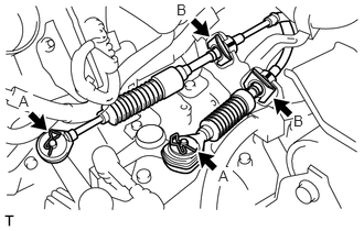
Remove the 2 clips A and 2 washers to disconnect the transmission control cable assembly from the floor shift selecting bellcrank assembly.
Remove the 2 clips B to separate the transmission control cable assembly from the control cable bracket.
82123
17.DISCONNECT NO. 3 ENGINE WIRE
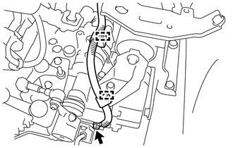
Remove the bolt to disconnect the No. 3 engine wire from the manual transaxle assembly.
Disengage the 2 clamps to separate the No. 3 engine wire from the engine mounting bracket LH.
82121
18.DISCONNECT ENGINE WIRE (w/ ABS)
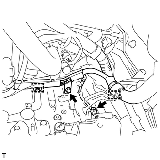
Disconnect the connector from the manual transaxle assembly.
Remove the bolt to separate the engine wire from the wire harness clamp bracket.
Disengage the 2 clamps to separate the engine wire from the wire harness clamp brackets.
82121
19.DISCONNECT ENGINE WIRE (w/o ABS)
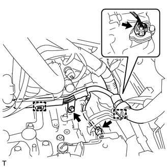
Disconnect the 2 connectors from the manual transaxle assembly.
Remove the bolt to separate the engine wire from the wire harness clamp bracket.
Disengage the 2 clamps to separate the engine wire from the wire harness clamp brackets.
33524B
20.REMOVE CONTROL CABLE BRACKET
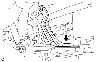
Remove the bolt and wire harness clamp bracket from the control cable bracket.
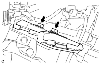
Remove the 2 bolts and control cable bracket from the manual transaxle assembly.
31470
21.SEPARATE CLUTCH RELEASE CYLINDER ASSEMBLY
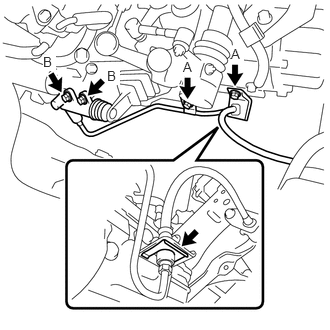
Remove the clip and 2 bolts A to separate the clutch release cylinder to flexible hose tube from the manual transaxle assembly.
Remove the 2 bolts B to separate the clutch release cylinder assembly from the manual transaxle assembly.
- NOTICE:
- ·
Suspend the clutch release cylinder assembly with a piece of rope so as not to place stress on the clutch line.
·Do not depress the clutch pedal.
58910C
22.REMOVE REAR CONSOLE BOX ASSEMBLY (w/ Console Box Lid)
58910C
23.REMOVE REAR CONSOLE BOX ASSEMBLY (w/o Console Box Lid)
57533B
24.REMOVE FRONT FLOOR CENTER BRACE
17410
25.REMOVE FRONT EXHAUST PIPE ASSEMBLY
26.REMOVE FRONT DRIVE SHAFT ASSEMBLIES
28100
27.REMOVE STARTER ASSEMBLY
51201
28.REMOVE FRONT SUSPENSION CROSSMEMBER SUB-ASSEMBLY
29.SUPPORT ENGINE ASSEMBLY
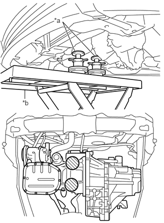
| *a | Attachment |
| *b | Engine Lifter |

|
Attachment Placement Positions |
Place the height adjustment attachments or plate lift attachments in the positions shown in the illustration and set the engine lifter underneath the engine assembly.
- NOTICE:
- ·
Place the height adjustment attachments or plate lift attachments so that the engine assembly with the manual transaxle assembly is level.
·As the engine assembly with the manual transaxle assembly is very heavy, be sure to support it securely.
·To prevent deformation of the No. 2 oil pan sub-assembly, never set any attachments against the No. 2 oil pan sub-assembly of the engine assembly.
12321B
30.REMOVE DRIVE SHAFT HEAT INSULATOR SUB-ASSEMBLY
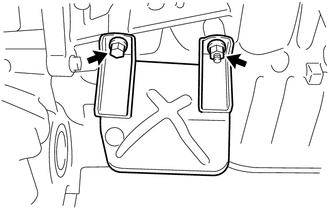
Using a 12 mm deep socket wrench, remove the nut.
Remove the bolt and drive shaft heat insulator sub-assembly from the engine assembly.
12313
31.REMOVE ENGINE MOVING CONTROL ROD BRACKET
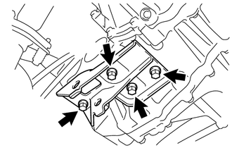
Remove the 4 bolts and engine moving control rod bracket from the manual transaxle assembly.
30300
32.REMOVE MANUAL TRANSAXLE ASSEMBLY
Set the transmission jack underneath the manual transaxle assembly.
- NOTICE:
-
Secure the manual transaxle assembly to the transmission jack using a suitable adapter, such as a rope or attachment.
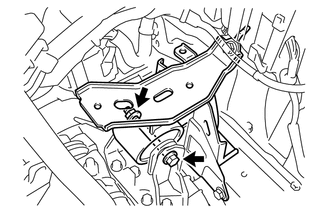
Remove the bolt and nut to separate the engine mounting insulator LH from the engine mounting bracket LH.
- HINT:
-
Turn the bolt while holding the nut.
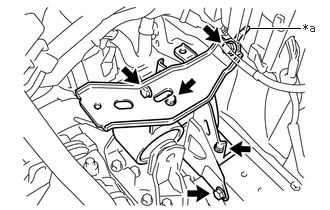
| *a | Hook |
Remove the 5 bolts.
Disengage the hook to remove the engine mounting insulator LH from the body.
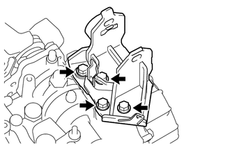
Remove the 4 bolts and engine mounting bracket LH from the manual transaxle assembly.
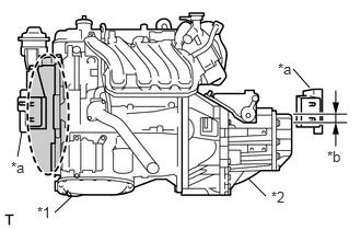
| *1 | Engine Assembly |
| *2 | Manual Transaxle Assembly |
| *a | Body |
| *b | Tilt 50 mm (1.97 in.) or less |

|
Watch for Interference |
Operate the engine lifter and transmission jack, and slowly tilt the engine assembly with the manual transaxle assembly 50 mm (1.97 in.) or less.
- NOTICE:
- ·
Do not allow the engine assembly and manual transaxle assembly to interfere with the body.
·Make sure that the engine assembly is not tilted more than necessary.
·Make sure that the wire harness and hoses are not being pulled.
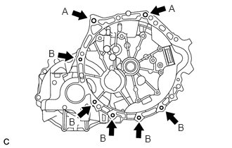
Remove the 7 bolts.
- HINT:
- ·
Bolt A: Remove from manual transaxle assembly side
·Bolt B: Remove from engine assembly side
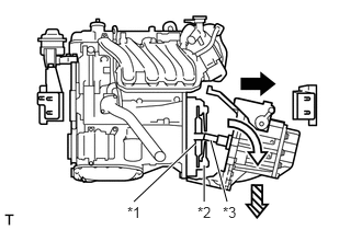
| *1 | Clutch Disc Assembly |
| *2 | Clutch Cover Assembly |
| *3 | Input Shaft |
Using the transmission jack, remove the manual transaxle assembly from the engine assembly according to the procedures shown in the illustration.
- NOTICE:
- ·
To prevent damage to the knock pins, do not pry between the manual transaxle assembly and engine assembly.
·To prevent damage to the input shaft, do not forcefully shake the manual transaxle assembly.
Move the manual transaxle assembly towards the left side of the vehicle and disengage the input shaft from the clutch disc assembly.
Tilt the manual transaxle assembly and pull the input shaft out from the clutch cover assembly.
Lower the manual transaxle assembly.
33.REMOVE WIRE HARNESS CLAMP BRACKET
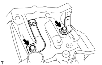
Remove the 2 bolts and 2 wire harness clamp brackets from the manual transaxle assembly.
33403K
34.REMOVE SPEEDOMETER DRIVEN HOLE COVER SUB-ASSEMBLY (w/ ABS)
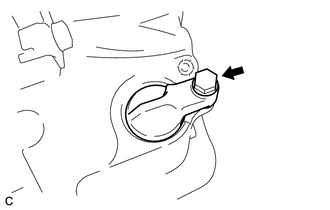
Remove the bolt and speedometer driven hole cover sub-assembly from the manual transaxle assembly.
Remove the O-ring from the speedometer driven hole cover sub-assembly.
83181G
35.REMOVE SPEEDOMETER SENSOR (w/o ABS)
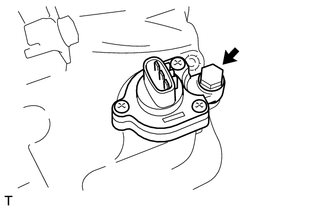
Remove the bolt and speedometer sensor from the manual transaxle assembly.
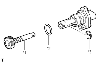
| *1 | Speedometer Driven Gear |
| *2 | O-ring |
| *3 | Clip |
Remove the clip and speedometer driven gear from the speedometer sensor.
Remove the O-ring from the speedometer sensor.