THEFT DETERRENT / KEYLESS ENTRY THEFT DETERRENT SYSTEM Theft Deterrent System cannot be Set or Unset
DESCRIPTION
When the engine switch is turned off and all doors, the luggage door*1, and the engine hood are closed, the theft deterrent system is set when doors are locked by wireless operation or entry operation*2. If all doors are closed but the luggage door*1 or engine hood is open when doors are locked by wireless operation or the entry operation, the theft deterrent system will be set when the luggage door*1 or engine hood is closed. Also, when the engine switch is turned on (IG) and the engine is run continuously for 2 seconds or more, or when the doors are unlocked by wireless operation or entry operation*2, the theft deterrent system is unset.
*1: for Sedan
*2: w/ Smart Entry and Start System
WIRING DIAGRAM
Refer to "System Diagram".
Click hereVehicle Interior>THEFT DETERRENT / KEYLESS ENTRY>THEFT DETERRENT SYSTEM>SYSTEM DIAGRAM
CAUTION / NOTICE / HINT
- NOTICE:
-
Inspect the fuses for circuits related to this system before performing the following procedure.
PROCEDURE
Check the wireless door lock control operation using the electrical key transmitter sub-assembly.
- Result:
Result Proceed to OK A NG (w/ Smart Entry and Start System) B NG (w/o Smart Entry and Start System) C
A
B
C
Open the driver side window.
Set the theft deterrent system.
Close all doors, luggage compartment door*1 and the engine hood.
*1: for Sedan
Lock the doors using wireless operation or entry operation*1.
*1: w/ Smart Entry and Start System
Wait for 30 seconds or more.
Unlock the driver door using the door lock knob.
Open the driver door and activate the theft deterrent system.
- Result:
Result Proceed to Theft deterrent system does not operate A Theft deterrent system operates B
A
B
Disconnect the driver side junction block assembly connector.
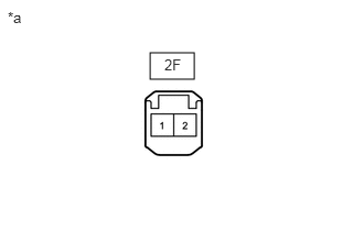
| *a | Front view of wire harness connector
(to Driver Side Junction Block Assembly) |
Measure the voltage according to the value(s) in the table below.
- Standard Voltage:
Tester Connection Switch Condition Specified Condition 2F-1 - Body ground Ignition switch ON 11 to 14 V 2F-1 - Body ground Ignition switch off Below 1 V
- Result:
Proceed to OK NG
OK
NG
Remove the body computer.
Click herePower Source / Network>POWER DISTRIBUTION>MAIN BODY ECU>REMOVAL
Disconnect the driver side junction block assembly connector.
Measure the resistance according to the value(s) in the table below.
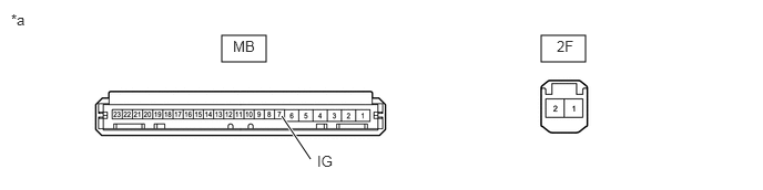
| *a | Component without harness connected
(Driver Side Junction Block Assembly) |
- | - |
- Standard Resistance:
Tester Connection Condition Specified Condition 2F-1 - MB-7 (IG) Always Below 1 Ω
- Result:
Proceed to OK NG
OK
NG
Remove the driver side junction block assembly with connectors still connected.
Click herePower Source / Network>POWER DISTRIBUTION>MAIN BODY ECU>REMOVAL
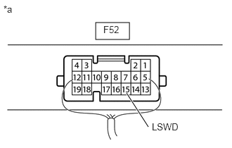
| *a | Component with harness connected
(Body Computer) |
Measure the voltage and check for pulse according to the value(s) in the table below.
- Standard Voltage:
Tester Connection Condition Specified Condition F52-15 (LSWD) - Body ground Front door RH*1 or LH*2 unlocked Below 1 V F52-15 (LSWD) - Body ground Front door RH*1 or LH*2 locked Pulse generation
*1: for RHD
*2: for LHD
- Result:
Result Proceed to OK A NG (for RHD) B NG (for LHD) C
A
B
C
Remove the driver side junction block assembly with connectors still connected.
Click herePower Source / Network>POWER DISTRIBUTION>MAIN BODY ECU>REMOVAL
Measure the voltage and check for pulses according to the value(s) in the table below.
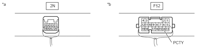
| *a | Component with harness connected
(Driver Side Junction Block Assembly) |
*b | Component with harness connected
(Body Computer) |
- Standard Voltage:
Tester Connection Condition Specified Condition 2N-1 - Body ground Front door RH*1 or LH*2 open Below 1 V 2N-1 - Body ground Front door RH*1 or LH*2 closed Pulse generation F52-14 (PCTY) - Body ground Front door LH*1 or RH*2 open Below 1 V F52-14 (PCTY) - Body ground Front door LH*1 or RH*2 closed Pulse generation F52-14 (PCTY) - Body ground Rear door RH open Below 1 V F52-14 (PCTY) - Body ground Rear door RH closed Pulse generation F52-14 (PCTY) - Body ground Rear door LH open Below 1 V F52-14 (PCTY) - Body ground Rear door LH closed Pulse generation
*1: for RHD
*2: for LHD
- Result:
Result Proceed to OK (for Sedan) A OK (for Hatchback) B NG (Front door RH) C NG (Front door LH) D NG (Rear door RH) E NG (Rear door LH) F
A
B
C
D
E
F
Remove the driver side junction block assembly with connectors still connected.
Click herePower Source / Network>POWER DISTRIBUTION>MAIN BODY ECU>REMOVAL
Measure the voltage and check for pulses according to the value(s) in the table below.
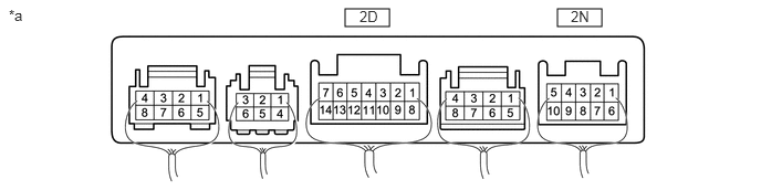
| *a | Component with harness connected
(Driver Side Junction Block Assembly) |
- | - |
- Standard Voltage:
Tester Connection Condition Specified Condition 2N-3 - Body ground Luggage compartment door open Below 1 V 2N-3 - Body ground Luggage compartment door closed Pulse generation 2D-9 - Body ground Engine hood open Below 1 V 2D-9 - Body ground Engine hood closed Pulse generation
- Result:
Result Proceed to NG (Luggage compartment door) A NG (Engine hood) B OK C
A
B
C
Remove the luggage compartment door lock assembly.
Click hereVehicle Interior>LIGHTING (INT)>BACK DOOR COURTESY SWITCH(for Sedan)>REMOVAL
Inspect the luggage compartment door lock assembly.
Click hereVehicle Interior>LIGHTING (INT)>BACK DOOR COURTESY SWITCH(for Sedan)>INSPECTION
- Result:
Proceed to OK NG
OK
NG
Disconnect the L5 luggage compartment door lock assembly connector.
Disconnect the 2N driver side junction block assembly connector.
Measure the resistance according to the value(s) in the table below.
- Standard Resistance:
Tester Connection Condition Specified Condition L5-3 (D+) - 2N-3 Always Below 1 Ω L5-2 (ACT-) - Body ground Always Below 1 Ω L5-3 (D+) or 2N-3 - Body ground Always 10 kΩ or higher
- Result:
Proceed to OK NG
OK
NG
Remove the body computer.
Click herePower Source / Network>POWER DISTRIBUTION>MAIN BODY ECU>REMOVAL
Disconnect the driver side junction block assembly connector.
Measure the resistance according to the value(s) in the table below.
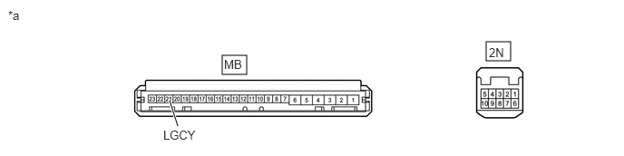
| *a | Component without harness connected
(Driver Side Junction Block Assembly) |
- | - |
- Standard Resistance:
Tester Connection Condition Specified Condition 2N-3 - MB-21 (LGCY) Always Below 1 Ω
- Result:
Proceed to OK NG
OK
NG
Remove the driver side junction block assembly with connectors still connected.
Click herePower Source / Network>POWER DISTRIBUTION>MAIN BODY ECU>REMOVAL
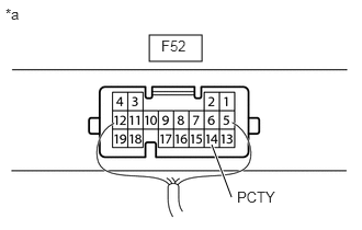
| *a | Component with harness connected
(Body Computer) |
Measure the voltage and check for pulse according to the value(s) in the table below.
- Standard Voltage:
Tester Connection Condition Specified Condition F52-14 (PCTY) - Body ground Back door open Below 1 V F52-14 (PCTY) - Body ground Back door closed Pulse generation
- Result:
Proceed to OK NG
OK
NG
Remove the driver side junction block assembly with connectors still connected.
Click herePower Source / Network>POWER DISTRIBUTION>MAIN BODY ECU>REMOVAL
Measure the voltage and check for pulses according to the value(s) in the table below.
| *a | Component with harness connected
(Driver Side Junction Block Assembly) |
- | - |
- Standard Voltage:
Tester Connection Condition Specified Condition 2N-3 - Body ground Back door open Below 1 V 2N-3 - Body ground Back door closed Pulse generation 2D-9 - Body ground Engine hood open Below 1 V 2D-9 - Body ground Engine hood closed Pulse generation
- Result:
Result Proceed to NG (Back door) A NG (Engine hood) B OK C
A
B
C
Disconnect the R2 back door lock assembly connector.
Disconnect the 2N driver side junction block assembly connector.
Measure the resistance according to the value(s) in the table below.
- Standard Resistance:
Tester Connection Condition Specified Condition R2-3 (D+) - 2N-3 Always Below 1 Ω R2-2 (ACT-) - Body ground Always Below 1 Ω R2-3 (D+) or 2N-3 - Body ground Always 10 kΩ or higher
- Result:
Proceed to OK NG
OK
NG
Remove the body computer.
Click herePower Source / Network>POWER DISTRIBUTION>MAIN BODY ECU>REMOVAL
Disconnect the driver side junction block assembly connector.
Measure the resistance according to the value(s) in the table below.
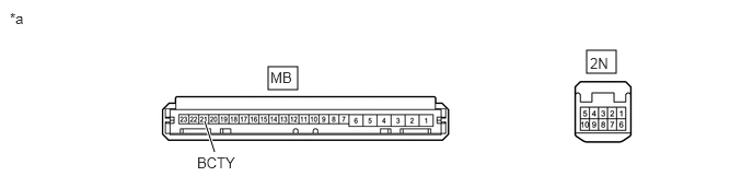
| *a | Component without harness connected
(Driver Side Junction Block Assembly) |
- | - |
- Standard Resistance:
Tester Connection Condition Specified Condition 2N-3 - MB-21 (BCTY) Always Below 1 Ω
- Result:
Proceed to OK NG
OK
NG
Remove the back door lock assembly.
Click hereVehicle Interior>LIGHTING (INT)>BACK DOOR COURTESY SWITCH(for Hatchback)>REMOVAL
Inspect the back door lock assembly.
Click hereVehicle Interior>LIGHTING (INT)>BACK DOOR COURTESY SWITCH(for Hatchback)>INSPECTION
- Result:
Proceed to OK NG
OK
NG
Disconnect the R2 back door lock assembly connector.
Disconnect the F52 body computer connector.
Measure the resistance according to the value(s) in the table below.
- Standard Resistance:
Tester Connection Condition Specified Condition R2-3 (D+) - F52-14 (PCTY)*1 Always Below 1 Ω R2-2 (ACT) - Body ground Always Below 1 Ω R2-3 (D+) or F52-14 (PCTY) - Body ground*1 Always 10 kΩ or higher
*1: Because the circuit includes a diode, make sure to connect the tester in the correct direction.
- Result:
Proceed to OK NG
OK
NG
Remove the hood lock assembly.
Click hereVehicle Interior>THEFT DETERRENT / KEYLESS ENTRY>ENGINE HOOD COURTESY SWITCH>REMOVAL
Inspect the hood lock assembly.
Click hereVehicle Interior>THEFT DETERRENT / KEYLESS ENTRY>ENGINE HOOD COURTESY SWITCH>INSPECTION
- Result:
Proceed to OK NG
OK
NG
Disconnect the A29 hood lock assembly connector.
Disconnect the 2D driver side junction block assembly connector.
Measure the resistance according to the value(s) in the table below.
- Standard Resistance:
Tester Connection Condition Specified Condition A29-1 - 2D-9 Always Below 1 Ω A29-2 - Body ground Always Below 1 Ω A29-1 or 2D-9 - Body ground Always 10 kΩ or higher
- Result:
Proceed to OK NG
OK
NG
Remove the body computer.
Click herePower Source / Network>POWER DISTRIBUTION>MAIN BODY ECU>REMOVAL
Disconnect the driver side junction block assembly connector.
Measure the resistance according to the value(s) in the table below.
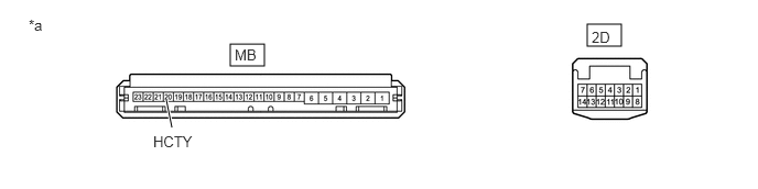
| *a | Component without harness connected
(Driver Side Junction Block Assembly) |
- | - |
- Standard Resistance:
Tester Connection Condition Specified Condition 2D-9 - MB-20 (HCTY) Always Below 1 Ω
- Result:
Proceed to OK NG
OK
NG
Remove the front door courtesy light switch assembly RH.
Click hereVehicle Interior>LIGHTING (INT)>FRONT DOOR COURTESY SWITCH>REMOVAL
Inspect the front door courtesy light switch assembly RH.
Click hereVehicle Interior>LIGHTING (INT)>FRONT DOOR COURTESY SWITCH>INSPECTION
- Result:
Result Proceed to OK (for RHD) A OK (for LHD) B NG C
A
B
C
Disconnect the F32 front door courtesy light switch assembly RH connector.
Disconnect the 2N driver side junction block assembly connector.
Measure the resistance according to the value(s) in the table below.
- Standard Resistance:
Tester Connection Condition Specified Condition F32-1 - 2N-1 Always Below 1 Ω F32-1 or 2N-1 - Body ground Always 10 kΩ or higher
- Result:
Proceed to OK NG
OK
NG
Remove the body computer.
Click herePower Source / Network>POWER DISTRIBUTION>MAIN BODY ECU>REMOVAL
Disconnect the driver side junction block assembly connector.
Measure the resistance according to the value(s) in the table below.
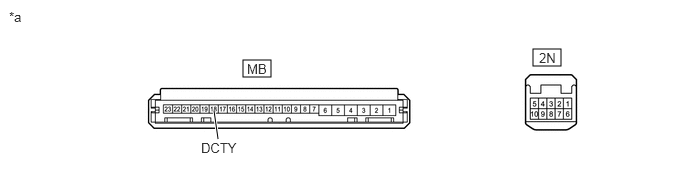
| *a | Component without harness connected
(Driver Side Junction Block Assembly) |
- | - |
- Standard Resistance:
Tester Connection Condition Specified Condition 2N-1 - MB-18 (DCTY) Always Below 1 Ω
- Result:
Proceed to OK NG
OK
NG
Disconnect the F32 front door courtesy light switch assembly RH connector.
Disconnect the F52 body computer connector.
Measure the resistance according to the value(s) in the table below.
- Standard Resistance:
Tester Connection Condition Specified Condition F32-1 - F52-14 (PCTY) Always Below 1 Ω F32-1 or F52-14 (PCTY) - Body ground Always 10 kΩ or higher
- Result:
Proceed to OK NG
OK
NG
Remove the front door courtesy light switch assembly LH.
Click hereVehicle Interior>LIGHTING (INT)>FRONT DOOR COURTESY SWITCH>REMOVAL
Inspect the front door courtesy light switch assembly LH.
Click hereVehicle Interior>LIGHTING (INT)>FRONT DOOR COURTESY SWITCH>INSPECTION
- Result:
Result Proceed to OK (for RHD) A OK (for LHD) B NG C
A
B
C
Disconnect the F31 front door courtesy light switch assembly LH connector.
Disconnect the F52 body computer connector.
Measure the resistance according to the value(s) in the table below.
- Standard Resistance:
Tester Connection Condition Specified Condition F31-1 - F52-14 (PCTY) Always Below 1 Ω F31-1 or F52-14 (PCTY) - Body ground Always 10 kΩ or higher
- Result:
Proceed to OK NG
OK
NG
Disconnect the F31 front door courtesy light switch assembly RH connector.
Disconnect the 2N driver side junction block assembly connector.
Measure the resistance according to the value(s) in the table below.
- Standard Resistance:
Tester Connection Condition Specified Condition F31-1 - 2N-1 Always Below 1 Ω F31-1 or 2N-1 - Body ground Always 10 kΩ or higher
- Result:
Proceed to OK NG
OK
NG
Remove the body computer.
Click herePower Source / Network>POWER DISTRIBUTION>MAIN BODY ECU>REMOVAL
Disconnect the driver side junction block assembly connector.
Measure the resistance according to the value(s) in the table below.
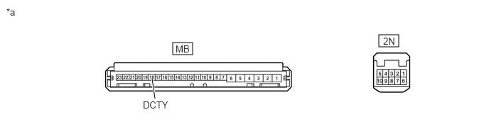
| *a | Component without harness connected
(Driver Side Junction Block Assembly) |
- | - |
- Standard Resistance:
Tester Connection Condition Specified Condition 2N-1 - MB-18 (DCTY) Always Below 1 Ω
- Result:
Proceed to OK NG
OK
NG
Remove the rear door courtesy light switch assembly RH.
Click hereVehicle Interior>LIGHTING (INT)>REAR DOOR COURTESY SWITCH>REMOVAL
Inspect the rear door courtesy light switch assembly RH.
Click hereVehicle Interior>LIGHTING (INT)>REAR DOOR COURTESY SWITCH>INSPECTION
- Result:
Proceed to OK NG
OK
NG
Disconnect the F34 rear door courtesy light switch assembly RH connector.
Disconnect the F52 body computer connector.
Measure the resistance according to the value(s) in the table below.
- Standard Resistance:
Tester Connection Condition Specified Condition F34-1 - F52-14 (PCTY) Always Below 1 Ω F34-1 or F52-14 (PCTY) - Body ground Always 10 kΩ or higher
- Result:
Proceed to OK NG
OK
NG
Remove the rear door courtesy light switch assembly LH.
Click hereVehicle Interior>LIGHTING (INT)>REAR DOOR COURTESY SWITCH>REMOVAL
Inspect the rear door courtesy light switch assembly LH.
Click hereVehicle Interior>LIGHTING (INT)>REAR DOOR COURTESY SWITCH>INSPECTION
- Result:
Proceed to OK NG
OK
NG
Disconnect the F33 rear door courtesy light switch assembly LH connector.
Disconnect the F52 body computer connector.
Measure the resistance according to the value(s) in the table below.
- Standard Resistance:
Tester Connection Condition Specified Condition F33-1 - F52-14 (PCTY) Always Below 1 Ω F33-1 or F52-14 (PCTY) - Body ground Always 10 kΩ or higher
- Result:
Proceed to OK NG
OK
NG
Remove the front door lock assembly RH.
for TMT Made: Click hereVehicle Interior>DOOR LOCK>FRONT DOOR LOCK(for TMT Made)>REMOVAL
for TMMIN Made: Click hereVehicle Interior>DOOR LOCK>FRONT DOOR LOCK(for TMMIN Made)>REMOVAL
Inspect the front door lock assembly RH.
for TMT Made: Click hereVehicle Interior>DOOR LOCK>FRONT DOOR LOCK(for TMT Made)>INSPECTION
for TMMIN Made: Click hereVehicle Interior>DOOR LOCK>FRONT DOOR LOCK(for TMMIN Made)>INSPECTION
- Result:
Result Proceed to OK A NG (for TMT Made) B NG (for TMMIN Made) C
A
B
C
Disconnect the G2 front door lock assembly RH connector.
Disconnect the F52 body computer connector.
Measure the resistance according to the value(s) in the table below.
- Standard Resistance:
Tester Connection Condition Specified Condition G2-7 (LSSR) - F52-15 (LSWD) Always Below 1 Ω G2-8 (E) - Body ground Always Below 1 Ω G2-7 or F52-15 (LSWD) - Body ground Always 10 kΩ or higher
- Result:
Proceed to OK NG
OK
NG
Remove the front door lock assembly LH.
Click hereVehicle Interior>DOOR LOCK>FRONT DOOR LOCK(for TMMIN Made)>REMOVAL
Inspect the front door lock assembly LH.
Click hereVehicle Interior>DOOR LOCK>FRONT DOOR LOCK(for TMMIN Made)>INSPECTION
- Result:
Proceed to OK NG
OK
NG
Disconnect the H3 front door lock assembly LH connector.
Disconnect the F52 body computer connector.
Measure the resistance according to the value(s) in the table below.
- Standard Resistance:
Tester Connection Condition Specified Condition H3-8 (LSSR) - F52-15 (LSWD) Always Below 1 Ω H3-7 (E) - Body ground Always Below 1 Ω H3-8 (LSSR) or F52-15 (LSWD) - Body ground Always 10 kΩ or higher
- Result:
Proceed to OK NG
OK
NG