BRAKE SYSTEM (OTHER) BRAKE BOOSTER(for RHD) INSTALLATION
PROCEDURE

 44610
1.INSTALL BRAKE BOOSTER ASSEMBLY
Install a new brake booster gasket to the brake booster assembly.
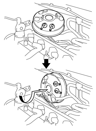
Rotate the brake booster assembly as shown in the illustration and install it.
- NOTICE:
- ·
Make sure the brake booster gasket does not fall off.
·Do not damage the brake tubes.
Temporarily install the brake booster assembly to the body with the 4 nuts.
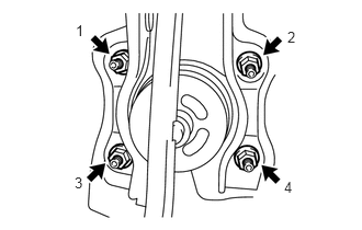
Tighten the 4 nuts in the order shown in the illustration.
- Torque:
- 9.0 N*m (92 kgf*cm, 80 in.*lbf)
Install the brake tubes to the body with a new brake tube clamp.
for 1NR-FE, 2NR-FE:
Connect the connector.
47264D
2.INSTALL BRAKE MASTER CYLINDER PUSH ROD CLEVIS
Install the clevis lock nut and brake master cylinder push rod clevis to the brake booster assembly.
- HINT:
-
Tighten the clevis lock nut after adjusting the brake pedal height.

|
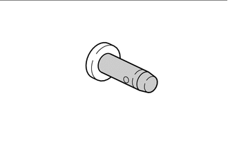
Lithium Soap Base Glycol Grease |
Apply lithium soap base glycol grease to the push rod pin.
Install the brake master cylinder push rod clevis to the brake pedal sub-assembly with the push rod pin and a new clip.
- NOTICE:
-
Install the push rod pin from the left side of the vehicle.
47101A
3.INSTALL BRAKE PEDAL RETURN SPRING
4.INSTALL WIRE HARNESS
84340
5.INSTALL STOP LIGHT SWITCH ASSEMBLY
12305
6.INSTALL ENGINE MOUNTING INSULATOR SUB-ASSEMBLY RH (for 1NZ-FE, 2NZ-FE)
12305
7.INSTALL ENGINE MOUNTING INSULATOR SUB-ASSEMBLY RH (for 1NR-FE, 2NR-FE)
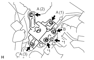
| *1 | Nut |
Temporarily install the engine mounting insulator sub-assembly RH to the timing chain cover assembly and vehicle with the 4 bolts and 2 nuts.
Tighten the 3 bolts A in the order shown in the illustration.
- Torque:
- Bolt A : 52 N*m (530 kgf*cm, 38 ft.*lbf)
Tighten the bolt B and 2 nuts.
- Torque:
- Bolt B and Nut : 52 N*m (530 kgf*cm, 38 ft.*lbf)
51441C
8.INSTALL ENGINE UNDER COVER RH (w/o Metal Type Under Cover)
51405A
9.INSTALL NO. 1 ENGINE UNDER COVER SUB-ASSEMBLY (w/ Metal Type Under Cover)
51451A
10.INSTALL CENTER ENGINE UNDER COVER (w/ Metal Type Under Cover)
17410
11.INSTALL FRONT EXHAUST PIPE ASSEMBLY (for 1NZ-FE, 2NZ-FE)
17410
12.INSTALL FRONT EXHAUST PIPE ASSEMBLY (for 1NR-FE, 2NR-FE)
for Sedan:
Click hereEngine / Hybrid System>1NR-FE FUEL>FUEL TANK(for TMT Made)>INSTALLATION
for Hatchback:
Click hereEngine / Hybrid System>1NR-FE FUEL>FUEL TANK(for TMT Made)>INSTALLATION
57533B
13.INSTALL FRONT FLOOR CENTER BRACE (for 1NZ-FE, 2NZ-FE)
57533B
14.INSTALL FRONT FLOOR CENTER BRACE (for 1NR-FE, 2NR-FE)
58910C
15.INSTALL REAR CONSOLE BOX ASSEMBLY (for 1NZ-FE, 2NZ-FE)
44772
16.CONNECT CHECK VALVE TO CONNECTOR TUBE HOSE (for Automatic Transaxle and CVT)
Connect the 2 check valve to connector tube hoses to the 2 brake vacuum check valve assemblies with the 2 hose clips.
44772
17.CONNECT CHECK VALVE TO CONNECTOR TUBE HOSE (for Manual Transaxle)
Connect the check valve to connector tube hose to the brake vacuum check valve assembly with the hose clip.
47201
18.INSTALL BRAKE MASTER CYLINDER SUB-ASSEMBLY
19.INSPECT AND ADJUST BRAKE PEDAL
20.INSPECT FOR EXHAUST GAS LEAK
- HINT:
-
Perform "Inspection After Repairs" after repairing or replacing the exhaust system.
- ·
for 1NR-FE:
Click hereEngine / Hybrid System>1NR-FE ENGINE CONTROL>SFI SYSTEM>INITIALIZATION
·for 2NR-FE:
Click hereEngine / Hybrid System>2NR-FE ENGINE CONTROL>SFI SYSTEM>INITIALIZATION