INTERIOR PANELS / TRIM UPPER INSTRUMENT PANEL REMOVAL
PROCEDURE

 1. PRECAUTION
- NOTICE:
-
After turning the ignition switch off, waiting time may be required before disconnecting the cable from the negative (-) battery terminal. Therefore, make sure to read the disconnecting the cable from the negative (-) battery terminal notices before proceeding with work.
-
Click hereGeneral>INTRODUCTION>REPAIR INSTRUCTION>PRECAUTION
2.DISCONNECT CABLE FROM NEGATIVE BATTERY TERMINAL
- CAUTION:
-
Wait at least 90 seconds after disconnecting the cable from the negative (-) battery terminal to disable the SRS system.
- NOTICE:
-
When disconnecting the cable, some systems need to be initialized after the cable is reconnected.
-
Click hereGeneral>INTRODUCTION>REPAIR INSTRUCTION>INITIALIZATION
62312B
3.DISCONNECT FRONT DOOR OPENING TRIM WEATHERSTRIP LH
Disconnect the front door opening trim weatherstrip LH.
62311B
4.DISCONNECT FRONT DOOR OPENING TRIM WEATHERSTRIP RH
- HINT:
-
Use the same procedure as for the LH side.
62212
5.REMOVE FRONT PILLAR GARNISH LH (w/ Curtain Shield Airbag)
62211
6.REMOVE FRONT PILLAR GARNISH RH (w/ Curtain Shield Airbag)
- HINT:
-
Use the same procedure as for the LH side.
62212
7.REMOVE FRONT PILLAR GARNISH LH (w/o Curtain Shield Airbag)
62211
8.REMOVE FRONT PILLAR GARNISH RH (w/o Curtain Shield Airbag)
- HINT:
-
Use the same procedure as for the LH side.
55409F
9.REMOVE NO. 2 INSTRUMENT PANEL SPEAKER PANEL SUB-ASSEMBLY
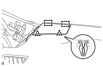
Disengage the 2 clips and 2 guides to remove the No. 2 instrument panel speaker panel sub-assembly.
55408F
10.REMOVE NO. 1 INSTRUMENT PANEL SPEAKER PANEL SUB-ASSEMBLY
- HINT:
-
Use the same procedure as for the No. 2 side.
55046A
11.REMOVE LOWER INSTRUMENT PANEL FINISH PANEL SUB-ASSEMBLY LH
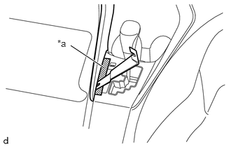
| *a | Protective Tape |
Apply protective tape as shown in the illustration.
Insert moulding remover at the position shown in the illustration.
Disengage the claw and 7 clips in the order shown in the illustration, and remove the lower instrument panel finish panel sub-assembly LH.
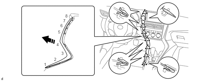

|
Remove in this Direction | - | - |
55045A
12.REMOVE LOWER INSTRUMENT PANEL FINISH PANEL SUB-ASSEMBLY RH
- HINT:
-
Use the same procedure as for the LH side.
86120
13.REMOVE RADIO RECEIVER ASSEMBLY WITH BRACKET (w/ Radio Receiver)
55412D
14.REMOVE CENTER INSTRUMENT CLUSTER FINISH PANEL (w/o Radio Receiver)
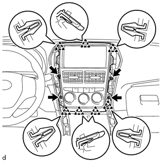
Remove the 4 screws.
Disengage the 7 clips to remove the center instrument cluster finish panel.
55900
15.REMOVE AIR CONDITIONING CONTROL ASSEMBLY (w/o Radio Receiver)
55661A
16.REMOVE INSTRUMENT PANEL REGISTER BEZEL
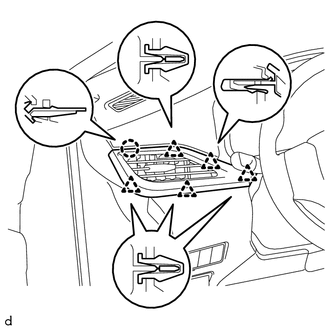
Disengage the 5 clips and claw to remove the instrument panel register bezel.
55411G
17.REMOVE NO. 1 INSTRUMENT CLUSTER FINISH PANEL (for LHD)
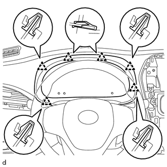
Disengage the 6 clips to remove the No. 1 instrument cluster finish panel.
55411G
18.REMOVE NO. 1 INSTRUMENT CLUSTER FINISH PANEL (for RHD)
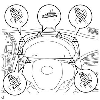
Disengage the 7 clips to remove the No. 1 instrument cluster finish panel.
83100
19.REMOVE COMBINATION METER ASSEMBLY
55550
20.REMOVE GLOVE COMPARTMENT DOOR ASSEMBLY
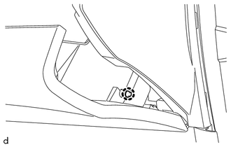
Disengage the claw to disconnect the glove compartment door stopper sub-assembly.
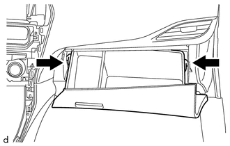
Slightly bend 2 stoppers in the directions indicated by the arrows in the illustration and pull the glove compartment door assembly until the stoppers are released.
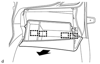
Open the glove compartment door assembly to approximately 60° from its closed position. Pull it horizontally in the direction indicated by the arrow to disengage the 4 hinges and remove the glove compartment door assembly.
55662A
21.REMOVE NO. 2 INSTRUMENT PANEL REGISTER BEZEL
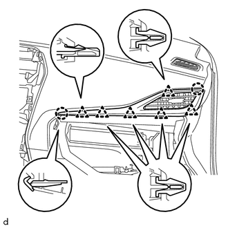
for LHD:
Disengage the 2 claws and 6 clips to remove the No. 2 instrument panel register bezel.
for RHD:
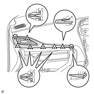
Disengage the 2 claws and the 6 clips.
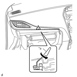
| *a | Tether Clip |
Twist the clip in the direction indicated by the arrow to remove the No. 2 instrument panel register bezel.
55606
22.REMOVE NO. 1 INSTRUMENT PANEL UNDER COVER SUB-ASSEMBLY
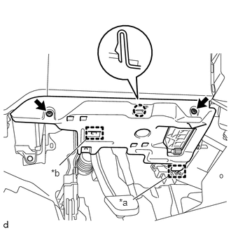
| *a | Guide |
| *b | Clamp |
Remove the 2 screws<B>.
Disengage the claw, guide and clamp to remove the No. 1 instrument panel under cover sub-assembly.
55480D
23.REMOVE LOWER INSTRUMENT PANEL FINISH PANEL ASSEMBLY
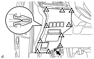
Remove the screw<B>.
Disengage the 10 clips to remove the lower instrument panel finish panel assembly.
Disconnect the connectors.
73900
24.REMOVE LOWER NO. 1 INSTRUMENT PANEL AIRBAG ASSEMBLY (for LHD with Driver Side Knee Airbag)
55432B
25.REMOVE LOWER INSTRUMENT PANEL FINISH PANEL (for LHD without Driver Side Knee Airbag)
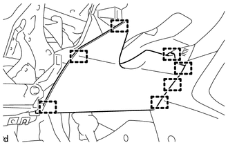
Disengage the 7 clips to remove the lower instrument panel finish panel.
55318C
26.REMOVE INSTRUMENT SIDE PANEL LH
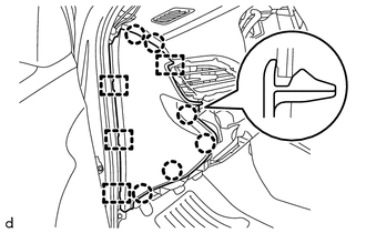
Disengage the 6 claws and 4 guides to remove the instrument side panel LH.
55317A
27.REMOVE INSTRUMENT SIDE PANEL RH
- HINT:
-
Use the same procedure as for the LH side.
58910C
28.REMOVE REAR CONSOLE BOX ASSEMBLY (for LHD)
58816D
29.REMOVE NO. 1 FRONT CONSOLE BOX INSERT (for LHD)
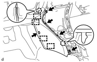
Remove the clip.
Remove the 4 screws.
Disengage the 2 claws and 4 guides to remove the No. 1 front console box insert.
55433B
30.REMOVE LOWER NO. 2 INSTRUMENT PANEL FINISH PANEL (for LHD)
w/ Smart Entry and Start System:
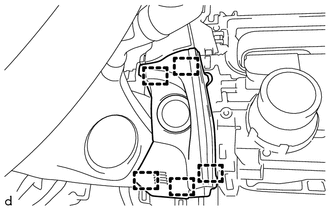
Disengage the 5 clips to remove the lower No. 2 instrument panel finish panel.
Disconnect the connector.
w/o Smart Entry and Start System:
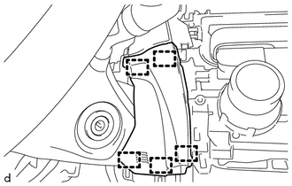
Disengage the 5 clips to remove the lower No. 2 instrument panel finish panel.
55302A
31.REMOVE UPPER INSTRUMENT PANEL SUB-ASSEMBLY
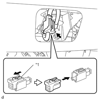
| *1 | Slider |
Slide the slider to release the lock, and then disconnect the connector.
- NOTICE:
-
When disconnecting any airbag connector, take care not to damage the airbag wire harness.
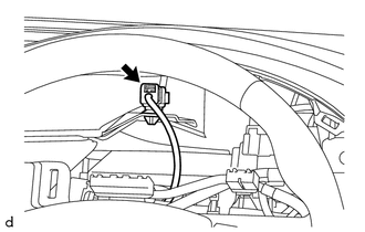
w/ Wire Harness:
Disconnect the connector.
Remove the bolt <C> and screw <A>.
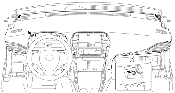
Remove the 2 clips.
Disengage the 10 clips and 2 dual lock fasteners.
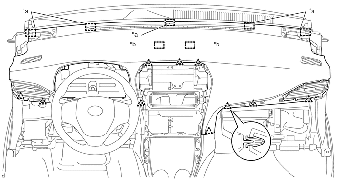
| *a | Guide | *b | Dual Lock fastener |
Disengage the 5 guides to remove the upper instrument panel sub-assembly.