FRONT SUSPENSION FRONT SUSPENSION MEMBER REMOVAL
PROCEDURE

 1.PLACE FRONT WHEELS FACING STRAIGHT AHEAD
2.REMOVE FRONT WHEELS
3.SECURE STEERING WHEEL
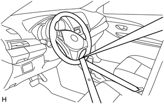
Secure the steering wheel with the seat belt in order to prevent it from rotating.
- HINT:
-
This operation is useful to prevent damage to the spiral cable.
45259A
4.REMOVE COLUMN HOLE COVER SILENCER SHEET
45209
5.SEPARATE STEERING SLIDING YOKE SUB-ASSEMBLY
45025D
6.SEPARATE NO. 1 STEERING COLUMN HOLE COVER SUB-ASSEMBLY
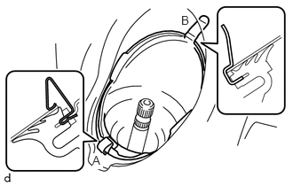
Disengage clip A and clip B from the body and separate the No. 1 steering column hole cover sub-assembly.
- NOTICE:
-
Do not damage clip B.
51451A
7.REMOVE CENTER ENGINE UNDER COVER (w/ Metal Type Under Cover)
51405A
8.REMOVE NO. 1 ENGINE UNDER COVER SUB-ASSEMBLY (w/ Metal Type Under Cover)
51442C
9.REMOVE ENGINE UNDER COVER LH (w/ Side Rail Reinforcement)
51441C
10.REMOVE ENGINE UNDER COVER RH (w/ Side Rail Reinforcement)
48819A
11.REMOVE FRONT STABILIZER BOLT LH (w/o Side Rail Reinforcement)
48819A
12.REMOVE FRONT STABILIZER BOLT RH (w/o Side Rail Reinforcement)
- HINT:
-
Use the same procedure described for the LH side.
48810
13.SEPARATE FRONT STABILIZER LINK ASSEMBLY LH (w/ Side Rail Reinforcement)
48820B
14.SEPARATE FRONT STABILIZER LINK ASSEMBLY RH (w/ Side Rail Reinforcement)
- HINT:
-
Use the same procedure described for the LH side.
45047
15.SEPARATE TIE ROD END SUB-ASSEMBLY LH
45046
16.SEPARATE TIE ROD END SUB-ASSEMBLY RH
- HINT:
-
Use the same procedure described for the LH side.
48069
17.SEPARATE FRONT LOWER NO. 1 SUSPENSION ARM SUB-ASSEMBLY LH
48068
18.SEPARATE FRONT LOWER NO. 1 SUSPENSION ARM SUB-ASSEMBLY RH
- HINT:
-
Use the same procedure described for the LH side.
51108A
19.REMOVE REAR SIDE RAIL REINFORCEMENT SUB-ASSEMBLY LH (w/ Side Rail Reinforcement)
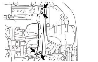
Remove the 4 bolts and rear side rail reinforcement sub-assembly LH.
51107A
20.REMOVE REAR SIDE RAIL REINFORCEMENT SUB-ASSEMBLY RH (w/ Side Rail Reinforcement)
- HINT:
-
Use the same procedure described for the LH side.
57533B
21.REMOVE FRONT FLOOR CENTER BRACE
17410
22.REMOVE FRONT EXHAUST PIPE ASSEMBLY
51201
23.REMOVE FRONT SUSPENSION CROSSMEMBER SUB-ASSEMBLY
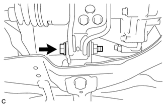
Remove the bolt and separate the engine moving control rod.
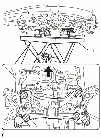
| *a | Plate Lift Attachment |
| *b | Engine Lifter |

|
Front of the Vehicle |

|
Attachment Placement Positions |
Place wooden blocks or plate lift attachments in the positions shown in the illustration and set an engine lifter underneath the front suspension crossmember sub-assembly.
- NOTICE:
- ·
Place the wooden blocks or plate lift attachments so that the front suspension crossmember sub-assembly is level.
·As the front suspension crossmember sub-assembly is very heavy, be sure to support it securely.
Remove the 6 bolts and front suspension crossmember sub-assembly.
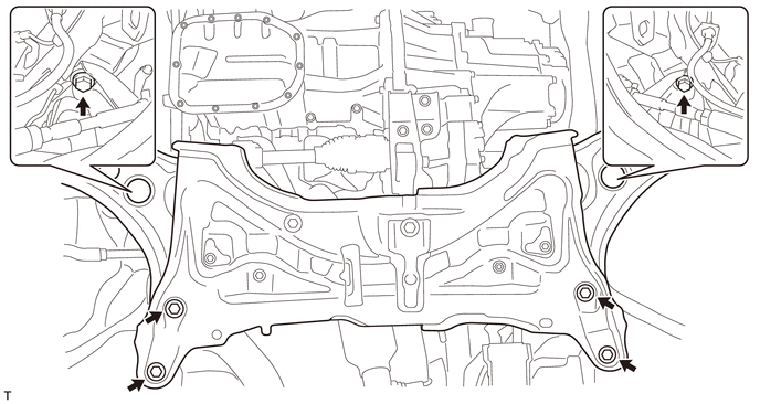
- NOTICE:
-
When lowering the front suspension crossmember sub-assembly, be careful not to damage the vehicle body or other components installed on the vehicle.
45025D
24.REMOVE NO. 1 STEERING COLUMN HOLE COVER SUB-ASSEMBLY
25.REMOVE STEERING LINK ASSEMBLY
48829A
26.REMOVE FRONT NO. 1 STABILIZER BRACKET LH
48824A
27.REMOVE FRONT NO. 1 STABILIZER BRACKET RH
- HINT:
-
Use the same procedure described for the LH side.
48811
28.REMOVE FRONT STABILIZER BAR
48069
29.REMOVE FRONT LOWER NO. 1 SUSPENSION ARM SUB-ASSEMBLY LH
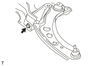
Remove the bolt and front lower No. 1 suspension arm sub-assembly LH from the front suspension crossmember sub-assembly.
48068
30.REMOVE FRONT LOWER NO. 1 SUSPENSION ARM SUB-ASSEMBLY RH
- HINT:
-
Use the same procedure described for the LH side.
12363A
31.REMOVE ENGINE MOVING CONTROL ROD (for Manual Transaxle)
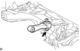
Remove the bolt and engine moving control rod from the front suspension crossmember sub-assembly.
12363A
32.REMOVE ENGINE MOVING CONTROL ROD (for CVT)
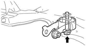
Remove the bolt and engine moving control rod from the front suspension crossmember sub-assembly.