1KR-FE ENGINE MECHANICAL CAMSHAFT REMOVAL
PROCEDURE

 17735
1.REMOVE AIR CLEANER ASSEMBLY WITH DUCT
19500D
2.REMOVE NO. 1 IGNITION COIL
3.SEPARATE ENGINE WIRE
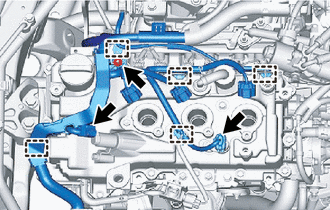
Disconnect the camshaft position sensor connector and camshaft timing oil control valve assembly (for exhaust side) connector.
Disengage the 5 clamps.
Remove the nut.
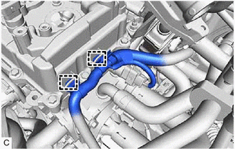
Disengage the 2 clamps.
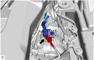
Disengage the clamp.
Disconnect the heated oxygen sensor connector.
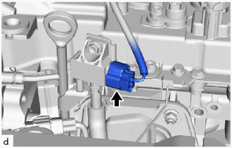
w/ Differential Pressure Sensor
Disconnect the differential pressure sensor connector.
29603B
4.DISCONNECT OIL LEVEL GAUGE GUIDE OIL HOSE
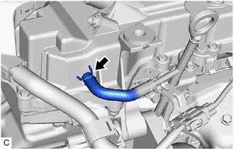
Slide the clip and disconnect the oil level gauge guide oil hose from the cylinder head cover sub-assembly.
11101J
5.REMOVE CAMSHAFT TIMING OIL CONTROL VALVE ASSEMBLY (for Exhaust Side)
11101E
6.REMOVE CAMSHAFT POSITION SENSOR (for Exhaust Side)
11201
7.REMOVE CYLINDER HEAD COVER SUB-ASSEMBLY
11213
8.REMOVE CYLINDER HEAD COVER GASKET
11302R
9.REMOVE TIMING GEAR COVER TIGHT PLUG
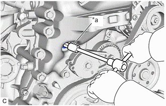
| *a | 8 mm Hexagon Socket Wrench |
Using an 8 mm socket hexagon wrench, remove the timing gear cover tight plug from the timing chain cover sub-assembly.
10.SET NO. 1 CYLINDER TO TDC/EXHAUST
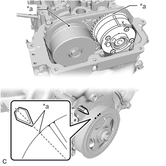
| *a | Timing Mark |
Turn the crankshaft pulley clockwise to align the timing mark of the pulley with the timing mark of the timing chain cover sub-assembly (set the No. 1 piston to TDC/exhaust).
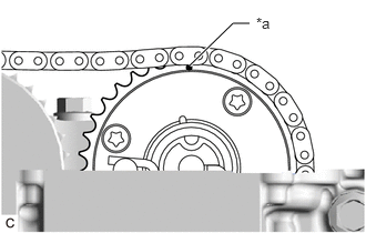
| *a | Timing Mark |
Make sure that the timing mark of the camshaft timing exhaust gear assembly is at the top.
- HINT:
-
If the timing mark is not at the top, turn the crankshaft pulley 1 revolution so that the timing mark comes to the top (set the No. 1 piston to TDC/exhaust).
11.REMOVE BRACKET
13070A
12.REMOVE CAMSHAFT TIMING EXHAUST GEAR ASSEMBLY
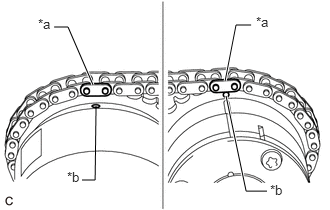
| *a | Paint Mark |
| *b | Timing Mark |
Place paint marks on the chain plates in alignment with the timing marks of the camshaft timing exhaust gear assembly and camshaft timing sprocket assembly.
Rotate the crankshaft 90° clockwise.
- NOTICE:
-
Do not allow a lifted valve and piston to come into contact with each other when removing the camshaft.
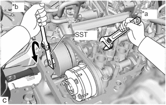
| *a | Hold |
| *b | Turn |
Using SST, loosen the bolts of the camshaft timing sprocket assembly while holding the hexagonal portion of the camshaft.
- SST
- 09249-37010
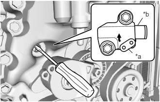
| *a | Stopper Plate |
| *b | Plunger |
Insert a screwdriver into the plug hole and turn the stopper plate of the No. 1 chain tensioner assembly clockwise to release the lock.
- HINT:
- ·
The plunger of the No. 1 chain tensioner assembly is locked.
·If the stopper plate is locked firmly, slightly turn the hexagonal portion of the camshaft to the right and left.
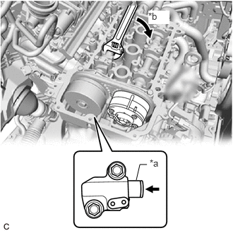
| *a | Plunger |
| *b | Turn |
While ensuring that the lock remains released, slightly turn the hexagonal portion of the camshaft clockwise so that the plunger of the No. 1 chain tensioner assembly is pushed by the chain sub-assembly.
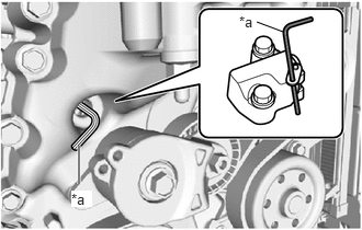
| *a | Hexagon Wrench |
Insert a 3 mm hexagon wrench into the stopper plate hole.
- HINT:
-
Hold the hexagon wrench with tape so that the hexagon wrench does not come off.
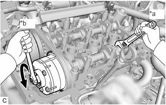
| *a | Hold |
| *b | Turn |
Remove the bolt of the camshaft timing exhaust gear assembly while holding the hexagonal portion of the No. 2 camshaft.
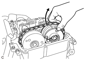
Remove the camshaft timing exhaust gear assembly.
13511
13.REMOVE CAMSHAFT
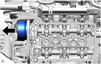
Slide the camshaft timing sprocket assembly toward the front of the engine until the No. 1 camshaft bearing cap comes off.
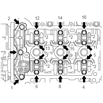
| *1 | No. 1 Camshaft Bearing Cap |
| *2 | No. 2 Camshaft Bearing Cap |
| *3 | No. 3 Camshaft Bearing Cap |
Remove the 15 bolts in the order shown in the illustration.
Remove the No. 1 camshaft bearing cap, 5 No. 2 camshaft bearing caps and No. 3 camshaft bearing cap.
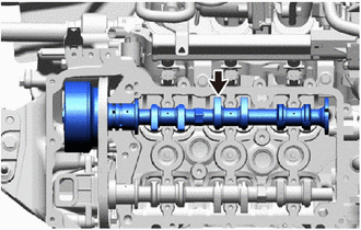
Remove the camshaft.
- HINT:
- ·
Remove the camshaft with the camshaft timing sprocket assembly.
13512
14.REMOVE NO. 2 CAMSHAFT
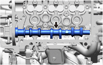
Remove the No. 2 camshaft.
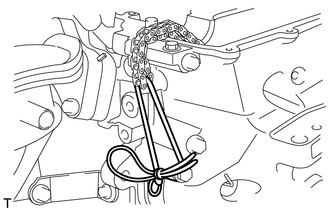
Using a piece of string or equivalent, secure the chain sub-assembly to prevent it from dropping.
13520
15.REMOVE CAMSHAFT TIMING SPROCKET ASSEMBLY
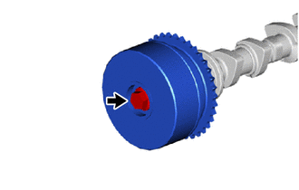
Remove the bolt and camshaft timing sprocket assembly from the camshaft.
13520
16.INSPECT CAMSHAFT TIMING SPROCKET ASSEMBLY
15678A
17.REMOVE OIL CONTROL VALVE FILTER