EA67F MANUAL TRANSMISSION / TRANSAXLE MANUAL TRANSAXLE ASSEMBLY INSTALLATION
PROCEDURE

 36100A
1.INSTALL TRANSFER & TRANSAXLE SETTING STUD BOLT
Clean the bolt holes.
Apply adhesive 1324 to 2 or 3 threads on one half of a new transfer and transaxle setting stud bolt A as shown in the illustration.
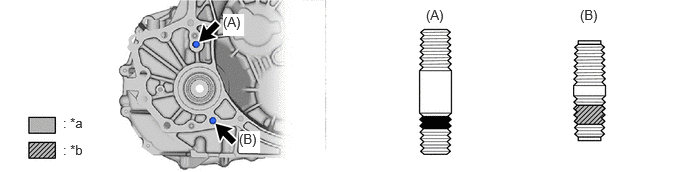
| *a | Toyota Genuine Adhesive 1324 | *b | Sealant |
- Adhesive:
Toyota Genuine Adhesive 1324, Three Bond 1324 or equivalent
- NOTICE:
- ·
Do not apply adhesive 1324 to the ends of the stud bolt.
·Install the stud bolt immediately after applying adhesive to prevent the adherence of foreign matter.
Install the 2 new transfer and transaxle setting stud bolts to the transaxle case positions shown in the illustration.
- Torque:
- 39.2 N*m (400 kgf*cm, 29 ft.*lbf)
- NOTICE:
-
Install the stud bolt so that the side that has sealant and adhesive is facing the automatic transaxle assembly.
- HINT:
-
Stud bolt length:
-
Stud bolt A: 69 mm (2.72 in.)
-
Stud bolt B: 47 mm (1.85 in.)
33111A
2.INSTALL MANUAL TRANSMISSION CASE PLUG
- HINT:
-
Perform this procedure only when replacement of the manual transaxle assembly is necessary.
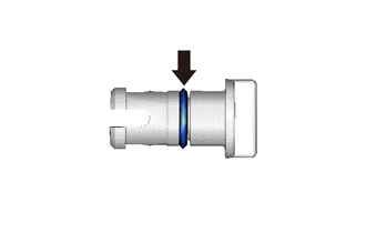
Coat the O-ring of a new transmission case plug assembly with gear oil.
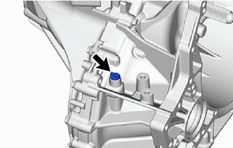
Install the transmission case plug assembly to the front transaxle case.
3.INSTALL WIRE HARNESS CLAMP BRACKET
Install the wire harness clamp to the manual transaxle assembly with the bolt.
- Torque:
- 10 N*m (102 kgf*cm, 7 ft.*lbf)
Install the 2 wire harness clamp bracket to the manual transaxle assembly with the 2 bolts.
- Torque:
- 10 N*m (102 kgf*cm, 7 ft.*lbf)
17568A
4.INSTALL EXHAUST PIPE SUPPORT STAY
Install the exhaust pipe support stay to the manual transaxle assembly with the 2 bolts.
- Torque:
- 43 N*m (438 kgf*cm, 32 ft.*lbf)
36100
5.TEMPORARILY TIGHTEN TRANSFER ASSEMBLY
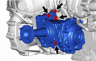
Temporarily install the transfer assembly to the manual transaxle assembly with the 2 bolts and 2 nuts.
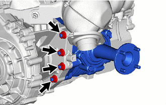
Temporarily install the 4 nuts.
30300
6.INSTALL MANUAL TRANSAXLE ASSEMBLY
Align the input shaft with the clutch disc and install the manual transaxle assembly to the engine assembly.
- NOTICE:
- ·
Make sure that the wire harness or similar items are not pinched between the contact surfaces.
·Do not forcibly pry on the manual transaxle assembly when installing it to the engine assembly.
·Do not apply excessive force to the manual transaxle assembly as this will break the input shaft.
·Make sure that the knock pins fit securely into the holes when installing the manual transaxle assembly to the engine assembly.
·Make sure that the contact surfaces of the engine assembly and manual transaxle assembly are flat against each other before tightening the bolts.
Install the transaxle assembly with the 7 bolts, in the sequence shown in the illustration.
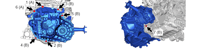
- Torque:
- for Bolt A : 64 N*m (653 kgf*cm, 47 ft.*lbf)
- for Bolt B : 46 N*m (469 kgf*cm, 34 ft.*lbf)
36100
7.INSTALL TRANSFER ASSEMBLY
Using SST and 17 mm union nut wrench, install the transfer assembly with the 2 bolts and 6 nuts.
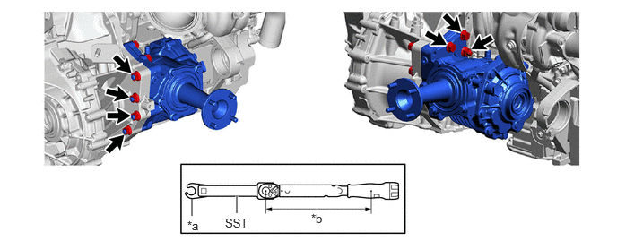
| *a | Union Nut Wrench | *b | Torque Wrench Fulcrum Length |
- SST
- 09961-00950
- Torque:
- Specified tightening torque : 68.6 N*m (700 kgf*cm, 51 ft.*lbf)
- HINT:
- ·
Calculate the torque wrench reading when changing the fulcrum length of the torque wrench.
Click hereGeneral>INTRODUCTION>REPAIR INSTRUCTION>PRECAUTION
·When using SST (fulcrum length of 150 mm (5.91 in.)) + torque wrench (fulcrum length of 255 mm (10.0 in.)): 40.2 N*m (410 kgf*cm, 30 ft.*lbf)
37117B
8.INSTALL PROPELLER SHAFT HEAT INSULATOR
Install the propeller shaft heat insulator to the transfer assembly with the 2 bolts.
- Torque:
- 25 N*m (255 kgf*cm, 18 ft.*lbf)
12364B
9.INSTALL NO. 2 ENGINE MOVING CONTROL ROD
Install the No. 2 engine moving control rod to the manual transaxle assembly with the 4 bolts.
- Torque:
- 44 N*m (449 kgf*cm, 32 ft.*lbf)
51201
10.INSTALL FRONT SUSPENSION CROSSMEMBER SUB-ASSEMBLY
Install the front suspension crossmember sub-assembly to the No. 2 engine moving control rod with the bolt.
- Torque:
- 170 N*m (1734 kgf*cm, 125 ft.*lbf)
17279
11.INSTALL TURBINE OUTLET ELBOW GASKET
25051
12.INSTALL EXHAUST MANIFOLD CONVERTER SUB-ASSEMBLY
82121
13.CONNECT ENGINE WIRE
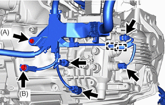
Connect the engine wire to the manual transaxle assembly with the 2 bolts.
- Torque:
- for Bolt A : 10 N*m (102 kgf*cm, 7 ft.*lbf)
- for Bolt B : 20 N*m (204 kgf*cm, 15 ft.*lbf)
Engage the 2 clamps to connect the engine wire to the wire harness bracket.
Connect the 4 connectors.
Connect the engine wire to the wire harness bracket with the bolt.
- Torque:
- 10 N*m (102 kgf*cm, 7 ft.*lbf)
Engage the 3 clamps to connect the engine wire to the wire harness clamp bracket.
31485
14.INSTALL NO. 2 CLUTCH FLEXIBLE HOSE BRACKET
Install the No. 2 clutch flexible hose bracket to the manual transaxle assembly with the bolt.
- Torque:
- 19 N*m (194 kgf*cm, 14 ft.*lbf)
31400
15.INSTALL CLUTCH RELEASE WITH BEARING CYLINDER ASSEMBLY
31224
16.INSTALL CLUTCH RELEASE BEARING PLATE
31407B
17.REMOVE CLUTCH RELEASE BLEEDER SUB-ASSEMBLY
18.INSPECT CLUTCH PIPE LINE
31407B
19.INSTALL CLUTCH RELEASE BLEEDER SUB-ASSEMBLY
31483
20.INSTALL BLEEDER CLUTCH RELEASE TUBE
28100
21.INSTALL STARTER ASSEMBLY
11363A
22.INSTALL FLYWHEEL HOUSING SIDE COVER
23.INSTALL ENGINE ASSEMBLY WITH TRANSAXLE
33820B
24.ADJUST TRANSMISSION CONTROL CABLE ASSEMBLY
25. INITIALIZATION AFTER RECONNECTING BATTERY TERMINAL
Click hereGeneral>SETUP>WHEN DISCONNECTING OR RECONNECTING BATTERY TERMINAL>WORK PROCEDURE
- HINT:
-
When disconnecting and reconnecting the battery, there is an automatic learning function that completes learning when the respective system is used.
-
Click hereGeneral>SETUP>WHEN DISCONNECTING OR RECONNECTING BATTERY TERMINAL>AUTOMATIC LEARNING CHART