LIGHTING (INT) LIGHTING SYSTEM Instrument Panel Illumination does not Turn On
DESCRIPTION
The power distribution box assembly controls the instrument panel illuminations.
WIRING DIAGRAM
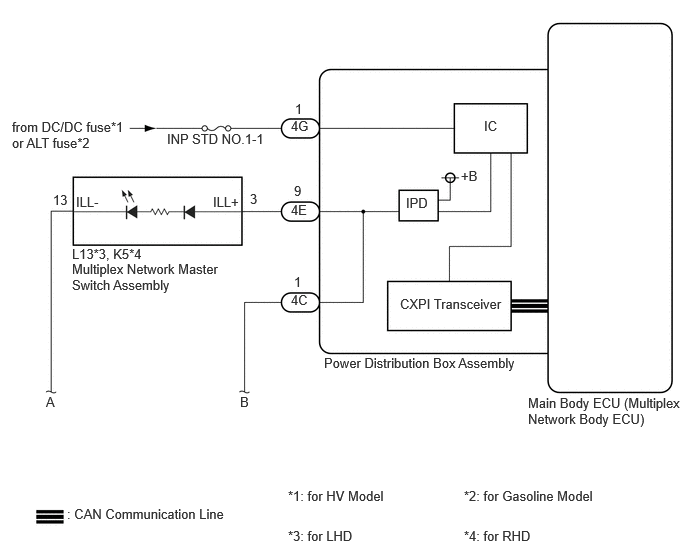
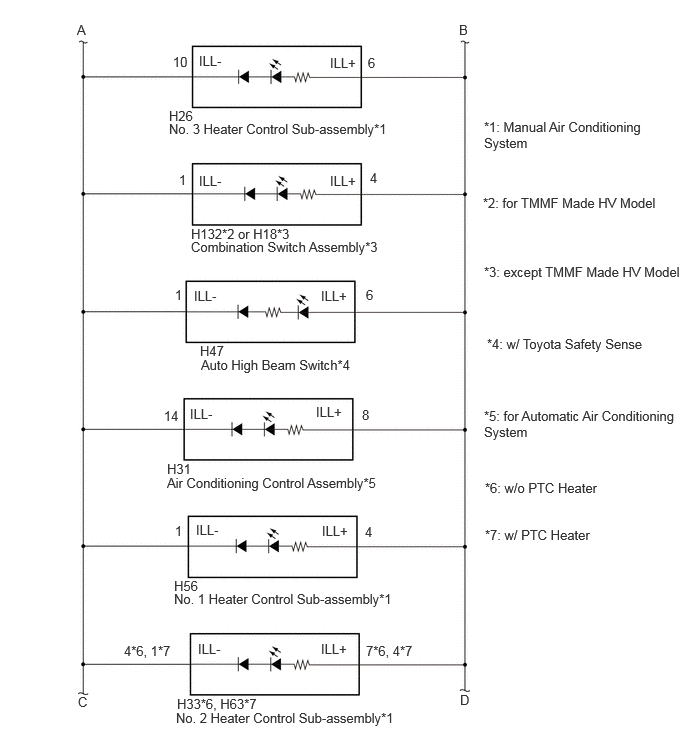
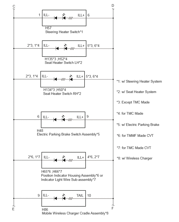
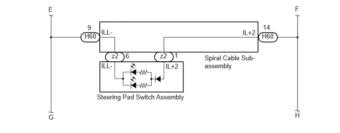
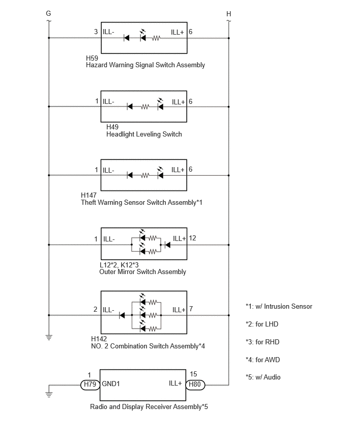
CAUTION / NOTICE / HINT
- NOTICE:
- ·
Inspect the fuses for circuits related to this system before performing the following procedure.
·Before replacing the main body ECU (multiplex network body ECU), refer to Service Bulletin.*1
*1: w/ Entry and Start System
PROCEDURE
Turn the light control switch to the TAIL position.
Read the Data List according to the display on the GTS.
- Body Electrical > Power Distribution Box > Data List
-
Tester Display Measurement Item Range Normal Condition Diagnostic Note Panel Light Fuse Shut Off Status Panel Light Fuse condition OFF or ON OFF: Fuse not shut off
ON: Fuse shut off-
- Body Electrical > Power Distribution Box > Data List
-
Tester Display Panel Light Fuse Shut Off Status - 50003 475 1298
- OK:
The Data List value displays "OFF".
- Result:
Proceed to OK NG
OK
NG
Read the Data List according to the display on the GTS.
- Body Electrical > Power Distribution Box > Data List
-
Tester Display Measurement Item Range Normal Condition Diagnostic Note Panel Light Input Signal Panel light input condition OFF or ON OFF: Light control switch not in tail position
ON: Light control switch in tail position-
- Body Electrical > Power Distribution Box > Data List
-
Tester Display Panel Light Input Signal - 50003 475 1295
- OK:
The GTS display changes.
- Result:
Proceed to OK NG
OK
for LHD: Click herePower Source / Network>POWER DISTRIBUTION>MAIN BODY ECU (for LHD)>REMOVAL
for RHD: Click herePower Source / Network>POWER DISTRIBUTION>MAIN BODY ECU (for RHD)>REMOVAL
NG
for LHD: Click herePower Source / Network>POWER DISTRIBUTION>MAIN BODY ECU (for LHD)>REMOVAL
for RHD: Click herePower Source / Network>POWER DISTRIBUTION>MAIN BODY ECU (for RHD)>REMOVAL
Disconnect the L12*1 or K12*2 outer mirror switch assembly connector.
*1: for LHD
*2: for RHD
Turn the light control switch to the TAIL position.
Read the Data List according to the display on the GTS.
- Body Electrical > Power Distribution Box > Data List
-
Tester Display Measurement Item Range Normal Condition Diagnostic Note Panel Light Fuse Shut Off Status Panel Light Fuse condition OFF or ON OFF: Fuse not shut off
ON: Fuse shut off-
- Body Electrical > Power Distribution Box > Data List
-
Tester Display Panel Light Fuse Shut Off Status - 50003 475 1298
- OK:
The Data List value displays "OFF".
- Result:
Proceed to OK NG
OK
NG
Disconnect the L13*1 or K5*2 multiplex network master switch assembly connector.
*1: for LHD
*2: for RHD
Connect the GTS to the DLC3.
Turn the light control switch to the TAIL position.
Read the Data List according to the display on the GTS.
- Body Electrical > Power Distribution Box > Data List
-
Tester Display Measurement Item Range Normal Condition Diagnostic Note Panel Light Fuse Shut Off Status Panel Light Fuse condition OFF or ON OFF: Fuse not shut off
ON: Fuse shut off-
- Body Electrical > Power Distribution Box > Data List
-
Tester Display Panel Light Fuse Shut Off Status - 50003 475 1298
- OK:
The Data List value displays "OFF".
- Result:
Result Proceed to OK A NG (w/ Toyota Safety Sense) B NG (w/o Toyota Safety Sense) C
A
B
C
Disconnect the H47 auto high beam switch connector.
Turn the light control switch to the TAIL position.
Read the Data List according to the display on the GTS.
- Body Electrical > Power Distribution Box > Data List
-
Tester Display Measurement Item Range Normal Condition Diagnostic Note Panel Light Fuse Shut Off Status Panel Light Fuse condition OFF or ON OFF: Fuse not shut off
ON: Fuse shut off-
- Body Electrical > Power Distribution Box > Data List
-
Tester Display Panel Light Fuse Shut Off Status - 50003 475 1298
- OK:
The Data List value displays "OFF".
- Result:
Proceed to OK NG
OK
NG
Disconnect the H49 headlight leveling switch connector.
Turn the light control switch to the TAIL position.
Read the Data List according to the display on the GTS.
- Body Electrical > Power Distribution Box > Data List
-
Tester Display Measurement Item Range Normal Condition Diagnostic Note Panel Light Fuse Shut Off Status Panel Light Fuse condition OFF or ON OFF: Fuse not shut off
ON: Fuse shut off-
- Body Electrical > Power Distribution Box > Data List
-
Tester Display Panel Light Fuse Shut Off Status - 50003 475 1298
- OK:
The Data List value displays "OFF".
- Result:
Result Proceed to OK A NG (w/ Steering Heater) B NG (w/o Steering Heater) C
A
B
C
Disconnect the H57 steering heater switch connector.
Turn the light control switch to the TAIL position.
Read the Data List according to the display on the GTS.
- Body Electrical > Power Distribution Box > Data List
-
Tester Display Measurement Item Range Normal Condition Diagnostic Note Panel Light Fuse Shut Off Status Panel Light Fuse condition OFF or ON OFF: Fuse not shut off
ON: Fuse shut off-
- Body Electrical > Power Distribution Box > Data List
-
Tester Display Panel Light Fuse Shut Off Status - 50003 475 1298
- OK:
The Data List value displays "OFF".
- Result:
Proceed to OK NG
OK
NG
Choose the model to be inspected.
- Result:
Result Proceed to for CVT (for TMMF Made CVT) A for CVT (for TMC Made CVT) B except CVT C
A
B
C
Disconnect the H65 posistion indicator housing assembly connector.
Turn the light control switch to the TAIL position.
Read the Data List according to the display on the GTS.
- Body Electrical > Power Distribution Box > Data List
-
Tester Display Measurement Item Range Normal Condition Diagnostic Note Panel Light Fuse Shut Off Status Panel Light Fuse condition OFF or ON OFF: Fuse not shut off
ON: Fuse shut off-
- Body Electrical > Power Distribution Box > Data List
-
Tester Display Panel Light Fuse Shut Off Status - 50003 475 1298
- OK:
The Data List value displays "OFF".
- Result:
Proceed to OK NG
OK
NG
Disconnect the H66 indicator light wire sub-assembly connector.
Turn the light control switch to the TAIL position.
Read the Data List according to the display on the GTS.
- Body Electrical > Power Distribution Box > Data List
-
Tester Display Measurement Item Range Normal Condition Diagnostic Note Panel Light Fuse Shut Off Status Panel Light Fuse condition OFF or ON OFF: Fuse not shut off
ON: Fuse shut off-
- Body Electrical > Power Distribution Box > Data List
-
Tester Display Panel Light Fuse Shut Off Status - 50003 475 1298
- OK:
The Data List value displays "OFF".
- Result:
Proceed to OK NG
OK
NG
Disconnect the H132*1 orH18*2 combination switch assembly connector.
*1: for HV Model
*2: for Gasoline Model
Turn the light control switch to the TAIL position.
Read the Data List according to the display on the GTS.
- Body Electrical > Power Distribution Box > Data List
-
Tester Display Measurement Item Range Normal Condition Diagnostic Note Panel Light Fuse Shut Off Status Panel Light Fuse condition OFF or ON OFF: Fuse not shut off
ON: Fuse shut off-
- Body Electrical > Power Distribution Box > Data List
-
Tester Display Panel Light Fuse Shut Off Status - 50003 475 1298
- OK:
The Data List value displays "OFF".
- Result:
Proceed to OK NG
OK
NG
Choose the model to be inspected.
- Result:
Result Proceed to w/ Electric Parking Brake A w/o Electric Parking Brake B
A
B
Disconnect the H48 electric Parking Brake Switch Assembly connector.
Turn the light control switch to the TAIL position.
Read the Data List according to the display on the GTS.
- Body Electrical > Power Distribution Box > Data List
-
Tester Display Measurement Item Range Normal Condition Diagnostic Note Panel Light Fuse Shut Off Status Panel Light Fuse condition OFF or ON OFF: Fuse not shut off
ON: Fuse shut off-
- Body Electrical > Power Distribution Box > Data List
-
Tester Display Panel Light Fuse Shut Off Status - 50003 475 1298
- OK:
The Data List value displays "OFF".
- Result:
Proceed to OK NG
OK
NG
Choose the model to be inspected.
- Result:
Result Proceed to w/ Wireless Charger A w/o Wireless Charger B
A
B
Disconnect the H86 mobile wireless charger cradle connector.
Turn the light control switch to the TAIL position.
Read the Data List according to the display on the GTS.
- Body Electrical > Power Distribution Box > Data List
-
Tester Display Measurement Item Range Normal Condition Diagnostic Note Panel Light Fuse Shut Off Status Panel Light Fuse condition OFF or ON OFF: Fuse not shut off
ON: Fuse shut off-
- Body Electrical > Power Distribution Box > Data List
-
Tester Display Panel Light Fuse Shut Off Status - 50003 475 1298
- OK:
The Data List value displays "OFF".
- Result:
Proceed to OK NG
OK
NG
Choose the model to be inspected.
- Result:
Result Proceed to w/ Seat Heater System A w/o Seat Heater System B
A
B
Disconnect the H135*1 ,H52*2 seat heater switch LH connector.
*1: Except TMC Made
*2: for TMC Made
Turn the light control switch to the TAIL position.
Read the Data List according to the display on the GTS.
- Body Electrical > Power Distribution Box > Data List
-
Tester Display Measurement Item Range Normal Condition Diagnostic Note Panel Light Fuse Shut Off Status Panel Light Fuse condition OFF or ON OFF: Fuse not shut off
ON: Fuse shut off-
- Body Electrical > Power Distribution Box > Data List
-
Tester Display Panel Light Fuse Shut Off Status - 50003 475 1298
- OK:
The Data List value displays "OFF".
- Result:
Proceed to OK NG
OK
NG
Disconnect the H134*3 ,H50*4 seat heater switch RH connector.
*1: Except TMC Made
*2: for TMC Made
Turn the light control switch to the TAIL position.
Read the Data List according to the display on the GTS.
- Body Electrical > Power Distribution Box > Data List
-
Tester Display Measurement Item Range Normal Condition Diagnostic Note Panel Light Fuse Shut Off Status Panel Light Fuse condition OFF or ON OFF: Fuse not shut off
ON: Fuse shut off-
- Body Electrical > Power Distribution Box > Data List
-
Tester Display Panel Light Fuse Shut Off Status - 50003 475 1298
- OK:
The Data List value displays "OFF".
- Result:
Proceed to OK NG
OK
NG
Choose the model to be inspected.
- Result:
Result Proceed to w/ Automatic Air Conditioning System A w/ Manual Air Conditioning System B
A
B
Disconnect the H31 air conditioning control assembly connector.
Turn the light control switch to the TAIL position.
Read the Data List according to the display on the GTS.
- Body Electrical > Power Distribution Box > Data List
-
Tester Display Measurement Item Range Normal Condition Diagnostic Note Panel Light Fuse Shut Off Status Panel Light Fuse condition OFF or ON OFF: Fuse not shut off
ON: Fuse shut off-
- Body Electrical > Power Distribution Box > Data List
-
Tester Display Panel Light Fuse Shut Off Status - 50003 475 1298
- OK:
The Data List value displays "OFF".
- Result:
Proceed to OK NG
OK
NG
Disconnect the H56 No. 1 heater control sub-assembly connector.
Turn the light control switch to the TAIL position.
Read the Data List according to the display on the GTS.
- Body Electrical > Power Distribution Box > Data List
-
Tester Display Measurement Item Range Normal Condition Diagnostic Note Panel Light Fuse Shut Off Status Panel Light Fuse condition OFF or ON OFF: Fuse not shut off
ON: Fuse shut off-
- Body Electrical > Power Distribution Box > Data List
-
Tester Display Panel Light Fuse Shut Off Status - 50003 475 1298
- OK:
The Data List value displays "OFF".
- Result:
Proceed to OK NG
OK
NG
Disconnect the H33*1 or H63*2 No. 2 heater control sub-assembly connector.
*1: w/o PTC Heater
*2: w/ PTC Heater
Turn the light control switch to the TAIL position.
Read the Data List according to the display on the GTS.
- Body Electrical > Power Distribution Box > Data List
-
Tester Display Measurement Item Range Normal Condition Diagnostic Note Panel Light Fuse Shut Off Status Panel Light Fuse condition OFF or ON OFF: Fuse not shut off
ON: Fuse shut off-
- Body Electrical > Power Distribution Box > Data List
-
Tester Display Panel Light Fuse Shut Off Status - 50003 475 1298
- OK:
The Data List value displays "OFF".
- Result:
Proceed to OK NG
OK
NG
Disconnect the H26 No. 3 heater control sub-assembly connector.
Turn the light control switch to the TAIL position.
Read the Data List according to the display on the GTS.
- Body Electrical > Power Distribution Box > Data List
-
Tester Display Measurement Item Range Normal Condition Diagnostic Note Panel Light Fuse Shut Off Status Panel Light Fuse condition OFF or ON OFF: Fuse not shut off
ON: Fuse shut off-
- Body Electrical > Power Distribution Box > Data List
-
Tester Display Panel Light Fuse Shut Off Status - 50003 475 1298
- OK:
The Data List value displays "OFF".
- Result:
Proceed to OK NG
OK
NG
Disconnect the z2 steering pad switch assembly connector.
Turn the light control switch to the TAIL position.
Read the Data List according to the display on the GTS.
- Body Electrical > Power Distribution Box > Data List
-
Tester Display Measurement Item Range Normal Condition Diagnostic Note Panel Light Fuse Shut Off Status Panel Light Fuse condition OFF or ON OFF: Fuse not shut off
ON: Fuse shut off-
- Body Electrical > Power Distribution Box > Data List
-
Tester Display Panel Light Fuse Shut Off Status - 50003 475 1298
- OK:
The Data List value displays "OFF".
- Result:
Proceed to OK NG
OK
NG
Disconnect the H60 spiral cable sub-assembly connector.
Turn the light control switch to the TAIL position.
Read the Data List according to the display on the GTS.
- Body Electrical > Power Distribution Box > Data List
-
Tester Display Measurement Item Range Normal Condition Diagnostic Note Panel Light Fuse Shut Off Status Panel Light Fuse condition OFF or ON OFF: Fuse not shut off
ON: Fuse shut off-
- Body Electrical > Power Distribution Box > Data List
-
Tester Display Panel Light Fuse Shut Off Status - 50003 475 1298
- OK:
The Data List value displays "OFF".
- Result:
Proceed to OK NG
OK
NG
Choose the model to be inspected.
- Result:
Result Proceed to w/ Intrusion Sensor A w/o Intrusion Sensor B
A
B
Disconnect the H147 theft warning sensor switch assembly connector.
Turn the light control switch to the TAIL position.
Read the Data List according to the display on the GTS.
- Body Electrical > Power Distribution Box > Data List
-
Tester Display Measurement Item Range Normal Condition Diagnostic Note Panel Light Fuse Shut Off Status Panel Light Fuse condition OFF or ON OFF: Fuse not shut off
ON: Fuse shut off-
- Body Electrical > Power Distribution Box > Data List
-
Tester Display Panel Light Fuse Shut Off Status - 50003 475 1298
- OK:
The Data List value displays "OFF".
- Result:
Proceed to OK NG
OK
NG
Choose the model to be inspected.
- Result:
Result Proceed to for AWD A Except AWD B
A
B
Disconnect the H142 No. 2 combination switch assembly connector.
Turn the light control switch to the TAIL position.
Read the Data List according to the display on the GTS.
- Body Electrical > Power Distribution Box > Data List
-
Tester Display Measurement Item Range Normal Condition Diagnostic Note Panel Light Fuse Shut Off Status Panel Light Fuse condition OFF or ON OFF: Fuse not shut off
ON: Fuse shut off-
- Body Electrical > Power Distribution Box > Data List
-
Tester Display Panel Light Fuse Shut Off Status - 50003 475 1298
- OK:
The Data List value displays "OFF".
- Result:
Proceed to OK NG
OK
NG
Disconnect the H59 hazard warning signal switch assembly connector.
Turn the light control switch to the TAIL position.
Read the Data List according to the display on the GTS.
- Body Electrical > Power Distribution Box > Data List
-
Tester Display Measurement Item Range Normal Condition Diagnostic Note Panel Light Fuse Shut Off Status Panel Light Fuse condition OFF or ON OFF: Fuse not shut off
ON: Fuse shut off-
- Body Electrical > Power Distribution Box > Data List
-
Tester Display Panel Light Fuse Shut Off Status - 50003 475 1298
- OK:
The Data List value displays "OFF".
- Result:
Result Proceed to OK A NG (w/ Audio) B NG (w/o Audio) C
A
B
C
Disconnect the H80 radio and display receiver assembly connector.
Turn the light control switch to the TAIL position.
Read the Data List according to the display on the GTS.
- Body Electrical > Power Distribution Box > Data List
-
Tester Display Measurement Item Range Normal Condition Diagnostic Note Panel Light Fuse Shut Off Status Panel Light Fuse condition OFF or ON OFF: Fuse not shut off
ON: Fuse shut off-
- Body Electrical > Power Distribution Box > Data List
-
Tester Display Panel Light Fuse Shut Off Status - 50003 475 1298
- OK:
The Data List value displays "OFF".
- Result:
Proceed to OK NG
OK
NG
Disconnect the L12 outer mirror switch assembly connector. (for LHD)
Disconnect the K12 outer mirror switch assembly connector. (for RHD)
Disconnect the L13 multiplex network master switch assembly connector. (for LHD)
Disconnect the K5 multiplex network master switch assembly connector. (for RHD)
Disconnect the H47 auto high beam switch connector. (w/ Toyota Safety Sense)
Disconnect the H49 headlight leveling switch connector.
Disconnect the H57 steering heater switch connector. (w/ steering heater system)
Disconnect the H65 position indicator housing assembly connector. (for TMMF Made CVT)
Disconnect the H66 indicator light wire sub-assembly connector. (for TMC Made CVT)
Disconnect the H132 combination switch assembly connector. (for TMMF Made HV Model)
Disconnect the H18 combination switch assembly connector. (for Gasoline Model)
Disconnect the H48 electric parking brake switch assembly connector. (w/ Electric Parking Brake)
Disconnect the H86 mobile wireless charger cradle assembly connector. (w/ wireless charger)
Disconnect the H135 seat heater switch LH connector. (Except TMC Made with Seat Heater)
Disconnect the H52 seat heater switch LH connector. (for TMC Made with Seat Heater)o
Disconnect the H134 seat heater switch RH connector. (Except TMC Made with Seat Heater)
Disconnect the H50 seat heater switch RH connector.. (for TMC Made with Seat Heater)
Disconnect the H31 air conditioning control assembly connector. (for Automatic Air Conditioning System)
Disconnect the H56 No. 1 heater control sub-assembly connector. (for Manual Air Conditioning System)
Disconnect the H33 No. 2 heater control sub-assembly connector. (for Manual Air Conditioning System without PTC Heater)
Disconnect the H63 No. 2 heater control sub-assembly connector.(for Manual Air Conditioning System with PTC Heater)
Disconnect the H26 No. 3 heater control sub-assembly connector. (for Manual Air Conditioning System)
Disconnect the z2 steering pad switch assembly connector.
Disconnect the H60 spiral cable sub-assembly connector.
Disconnect the H59 hazard warning signal switch assembly connector.
Disconnect the H80 radio and display receiver assembly connector. (w/ Audio)
Disconnect the cable from the negative (-) auxiliary battery terminal.
Disconnect the 4E and 4C power distribution box assembly connectors.
Measure the resistance according to the value(s) in the table below.
- Standard Resistance:
Tester Connection Condition Specified Condition L12-12 (ILL+) or 4C-1 - Body ground*1 Always Below 1 Ω K12-12 (ILL+) or 4C-1 - Body ground*2 Always Below 1 Ω L13-12 (ILL+) or 4E-9 - Body ground*1 Always Below 1 Ω K5-3 (ILL+) or 4E-9 - Body ground*2 Always Below 1 Ω H47-6 (ILL+) or 4C-1 - Body ground*3 Always Below 1 Ω H49-6 (ILL+) or 4C-1 - Body ground Always Below 1 Ω H57-6 (ILL+) or 4C-1 - Body ground*4 Always Below 1 Ω H65-4 (ILL+) or 4C-1 - Body ground*5 Always Below 1 Ω H66-2 (ILL+) or 4C-1 - Body ground*6 Always Below 1 Ω H132-4 (ILL+) or 4C-1 - Body ground*7 Always Below 1 Ω H18-4 (ILL+) or 4C-1 - Body ground*8 Always Below 1 Ω H48-9 (ILL+) or 4C-1 - Body ground*9 Always Below 1 Ω H86-10 (TAIL) or 4C-1 - Body ground*10 Always Below 1 Ω H135-5 (ILL+) or 4C-1 - Body ground*11 Always Below 1 Ω H52-6 (ILL+) or 4E-9 - Body ground*12 Always Below 1 Ω H134-5 (ILL+) or 4C-1 - Body ground*11 Always Below 1 Ω H50-6 (ILL+) or 4E-9 - Body ground*12 Always Below 1 Ω H31-8 (ILL+) or 4C-1 - Body ground*13 Always Below 1 Ω H56-4 (ILL+) or 4C-1 - Body ground*14 Always Below 1 Ω H33-7 (ILL+) or 4C-1 - Body ground*15 Always Below 1 Ω H63-4 (ILL+) or 4C-1 - Body ground*16 Always Below 1 Ω H26-6 (ILL+) or 4C-1 - Body ground*14 Always Below 1 Ω z2-1 (ILL+2) or 4C-1 - Body ground Always Below 1 Ω H60-14 (IL+2) or 4C-1 - Body ground Always Below 1 Ω H59-6 (ILL+) or 4C-1 - Body ground Always Below 1 Ω H80-15 (ILL+) or 4C-1 - Body ground*17 Always Below 1 Ω
*1: for LHD
*2: for RHD
*3: w/ Toyota Safety Sense
*4: w/ steering heater system
*5: for TMMF Made CVT
*6: for TMC Made CVT
*7: for TMMF Made HV Model
*8: except TMMF Made HV Model
*9: w/ Electric Parking Brake
*10: w/ wireless charger
*11: Except TMC Made with Seat Heater
*12: for TMC Made with Seat Heater
*13: for Automatic Air Conditioning System
*14: for Manual Air Conditioning System
*15: for Manual Air Conditioning System without PTC Heater
*16: for Manual Air Conditioning System with PTC Heater
*17: w/ Audio
- Result:
Proceed to OK NG
OK
for LHD: Click herePower Source / Network>POWER DISTRIBUTION>MAIN BODY ECU (for LHD)>REMOVAL
for RHD: Click herePower Source / Network>POWER DISTRIBUTION>MAIN BODY ECU (for RHD)>REMOVAL
NG