Home › ENGINE › 1KR-FE ENGINE MECHANICAL › ENGINE ASSEMBLYREMOVAL
Removal / installation · Vehicles built from Nov 2005
Versions by build date: Aug 2005 – Oct 2005 from Nov 2005
1.
CLUTCH POSITION ADJUSTMENT (for Multi-Mode Manual Transaxle)
(Click here )
2.
DISCHARGE FUEL SYSTEM PRESSURE
(Click here )
3.
REMOVE BATTERY
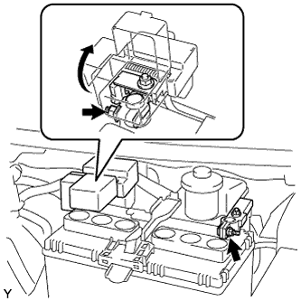
Disconnect the negative battery terminal.
Disconnect the positive battery terminal.
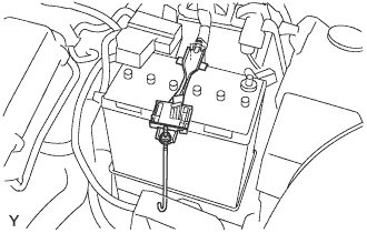
Loosen the nut, and remove the battery carrier clamp. Remove the battery from the vehicle.
5.
REMOVE BATTERY CARRIER
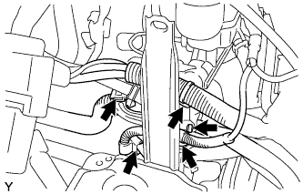
Disengage the 5 clamps, and separate the engine wire harness.
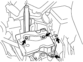
Remove the 4 bolts, and remove the battery carrier.
6.
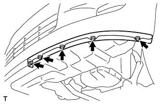
REMOVE FRONT SPOILER COVER LH (w/ Front Spoiler Cover LH)
Remove the 5 screws and the front spoiler cover.
7.
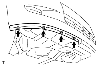
REMOVE FRONT SPOILER COVER (w/ Front Spoiler Cover)
Remove the 4 screws and the front spoiler cover.
8.
REMOVE ENGINE UNDER COVER LH
9.
REMOVE ENGINE UNDER COVER RH
10.
DRAIN ENGINE COOLANT
CAUTION:
To avoid the danger of being burned, do not remove the radiator cap sub-assembly while the engine and radiator assembly are still hot. Thermal expansion will cause hot engine coolant and steam to blow out from the radiator assembly.
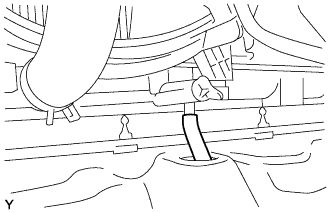
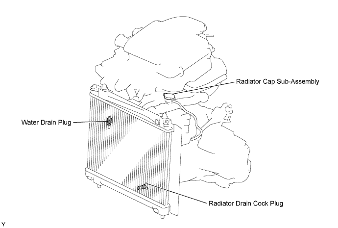
Install a vinyl hose onto the radiator side. Loosen the radiator drain cock plug.
Remove the radiator cap sub-assembly.
Loosen the water drain plug, then drain the coolant.
11.
DRAIN TRANSAXLE OIL (for Manual Transaxle)
Remove the filler plug and gasket.
Remove the drain plug and gasket, and then drain the manual transaxle oil.
Install a new gasket and the drain plug.
Torque:
39 N*m{
400 kgf*cm
, 29 ft.*lbf
}
12.
DRAIN TRANSAXLE OIL (for Multi-Mode Manual Transaxle)
Remove the filler plug and the gasket.
Remove the drain plug and gasket and drain the transaxle oil.
Install a new gasket and the drain plug.
Torque:
39 N*m{
400 kgf*cm
, 29 ft.*lbf
}
13.
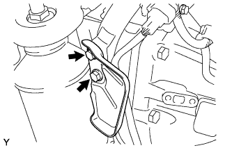
REMOVE EGR INLET EXHAUST MANIFOLD PLATE
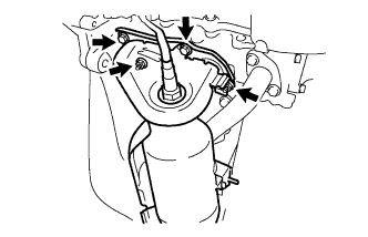
Remove the 2 bolts and the EGR inlet exhaust manifold plate.
14.
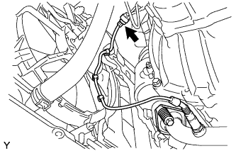
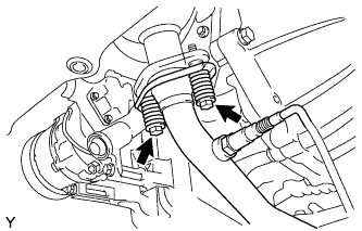
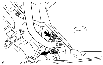
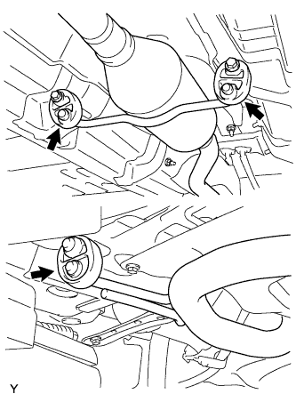
REMOVE EXHAUST PIPE ASSEMBLY FRONT
Disconnect the oxygen sensor connector, and disengage the 3 wire harness clamps.
Remove the 2 bolts and compression springs, and separate the exhaust pipe front from the exhaust manifold.
Remove the 2 bolts and compression springs, and separate the exhaust pipe front from the exhaust pipe tail.
Remove the 3 supports, and remove the exhaust pipe front.
16.
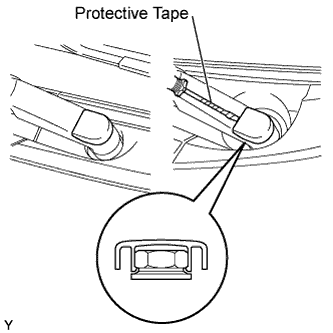
REMOVE FRONT WIPER ARM HEAD CAP
Using a screwdriver with its tip wrapped in protective tape, disengage the claw and remove the 2 front wiper arm head caps.
17.
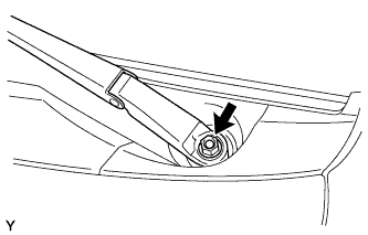
REMOVE FRONT WIPER ARM AND BLADE ASSEMBLY LH
Operate the wiper, then stop the windshield wiper motor in the automatic stop position.
Remove the nut and front wiper arm.
18.
REMOVE FRONT WIPER ARM AND BLADE ASSEMBLY RH
HINT:
Use the same procedure as for the LH side.
19.
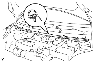
REMOVE HOOD TO COWL TOP SEAL
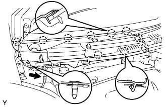
Disengage the 7 clips and remove the hood to cowl top seal.
20.
REMOVE COWL TOP VENTILATOR LOUVER SUB-ASSEMBLY (for LHD)
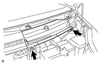
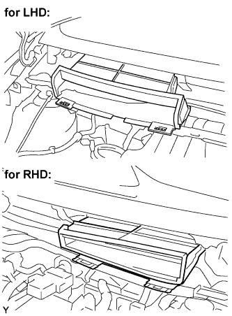
Disengage the 2 hooks and remove cowl top ventilator louver center No. 1.
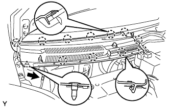
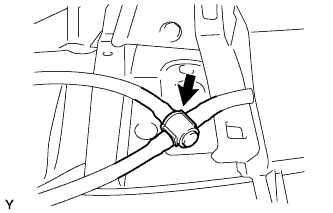
Disconnect the washer hose. Disengage the 11 claws and clip.
Disconnect the washer hose and remove the cowl top ventilator louver sub-assembly.
21.
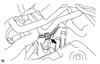
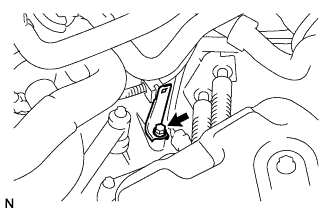
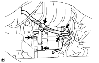
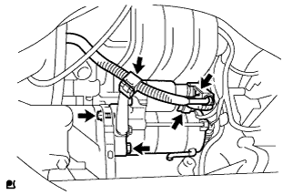
REMOVE COWL TOP VENTILATOR LOUVER LH (for LHD)
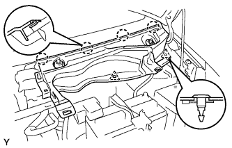
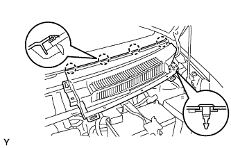
Remove the 2 clips.
Disengage the 4 claws and remove the cowl top ventilator louver LH.
22.
REMOVE COWL TOP VENTILATOR LOUVER SUB-ASSEMBLY (for RHD)
Disconnect the washer hose.
Disengage the 10 claws and clip and remove the cowl top ventilator louver sub-assembly.
23.
REMOVE COWL TOP VENTILATOR LOUVER LH (for RHD)
Remove the clip.
Disengage the 4 claws and remove the cowl top ventilator louver LH.
24.
REMOVE FRONT WIPER MOTOR AND LINK ASSEMBLY
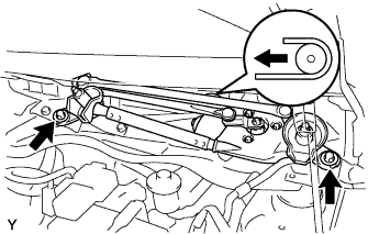
Remove the 2 bolts.
Slide the wiper link. Disengage the meshing of the rubber pin, then disconnect the connector and remove the front wiper motor and link.
25.
REMOVE COWL TO REGISTER DUCT SUB-ASSEMBLY NO. 2
Disengage the claws, and remove cowl to resister duct No. 2.
26.
REMOVE COWL TOP PANEL OUTER
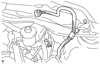
Disengage the clamp, and separate the wiper motor connector.
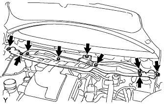
Remove the 9 bolts and the cowl top panel outer.
27.
REMOVE AIR CLEANER CAP SUB-ASSEMBLY
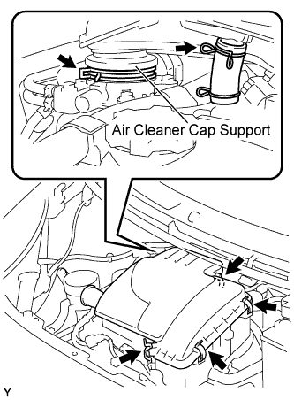
Remove the 4 clamps.
Remove the 2 clamps and remove the air cleaner cap.
28.
REMOVE AIR CLEANER FILTER ELEMENT SUB-ASSEMBLY
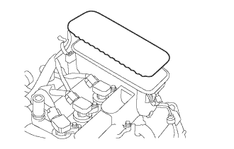
Remove the air cleaner filter element from the cylinder head cover.
29.
REMOVE VENTILATION HOSE NO. 2
30.
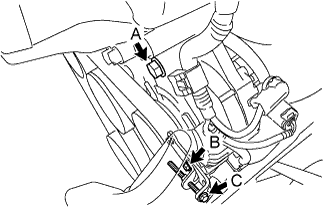
REMOVE FAN AND GENERATOR V BELT
Loosen bolt A.
Loosen bolt B.
Loosen bolt C.
Release the drive belt tension and remove the fan and generator V belt.
31.
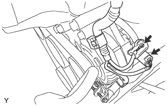
REMOVE GENERATOR ASSEMBLY
Disconnect the connector.
Remove the terminal cap.
Remove the nut and separate terminal B.
Disengage the 2 clamps and separate the wire harness.
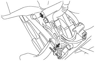
Remove the 2 bolts and the generator.
32.
REMOVE FAN BELT ADJUSTING BAR
Remove the bolt and the fan belt adjusting bar.
33.
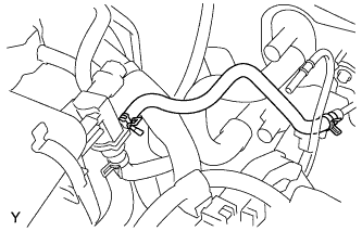
DISCONNECT FUEL VAPOR FEED HOSE NO. 1
Disconnect the fuel vapor feed hose from the vacuum switching valve.
34.
DISCONNECT WIRE HARNESS (for Multi-Mode Manual Transaxle)
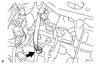
Remove the bolt, then disconnect the wire harness.
35.
DISCONNECT CONNECTOR (for Multi-Mode Manual Transaxle)
Disconnect the shift stroke sensor connector.
Disconnect the select stroke sensor connector.
Disconnect the transmission revolution sensor connector.
Disconnect the back-up light switch connector.
Disconnect the neutral start switch connector.
Disconnect the shift and select motor connectors.
36.
SEPARATE CLUTCH RELEASE CYLINDER ASSEMBLY (for Manual Transaxle)
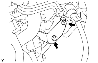
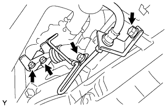
Remove the 2 bolts and the release cylinder heat insulator.
Remove the 4 bolts, then separate the clutch release cylinder.
HINT:
Using a piece of rope or the equivalent, hang the clutch release cylinder so as not to apply excessive load to the clutch pipe.
37.
SEPARATE TRANSMISSION CONTROL CABLE ASSEMBLY (for Manual Transaxle)
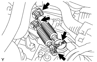
Remove the 2 clips and the 2 washers, and disconnect the 2 cables from the transaxle.
Remove the 2 clips and disconnect the 2 cables from the control cable bracket.
38.
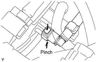
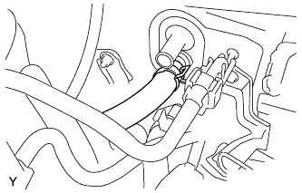
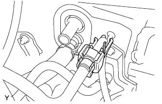
DISCONNECT BOOSTER VACUUM TUBE
Pinch the retainer as illustrated, then pull the vacuum hose connector out of the pipe.
39.
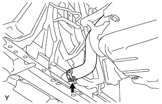
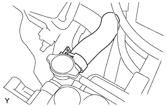
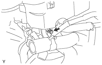
DISCONNECT RADIATOR HOSE NO. 1
40.
DISCONNECT RADIATOR HOSE NO. 2
41.
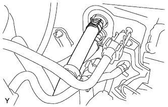
DISCONNECT HEATER WATER OUTLET HOSE A(FROM HEATER UNIT)
42.
DISCONNECT HEATER WATER INLET HOSE A
43.
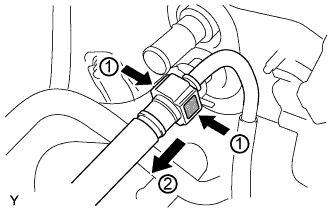
SEPARATE FUEL TUBE SUB-ASSEMBLY
Remove fuel pipe clamp No. 1.
Pinch the retainer as illustrated, then pull the fuel tube connector out of the pipe.
NOTICE:
Remove any dirt and foreign matter from the fuel tube connector before performing this work.
Do not allow any scratches or foreign matter on the parts when disconnecting, as the fuel tube connector has the O-rings that seals the pipe.
Perform this work by hand. Do not use any tools.
Do not forcibly bend, twist or turn the nylon tube.
Protect the disconnected part by covering it with a vinyl bag after disconnecting the fuel tube.
If the fuel tube connector and pipe are stuck, push and pull to release them.
44.
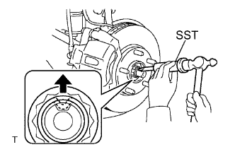
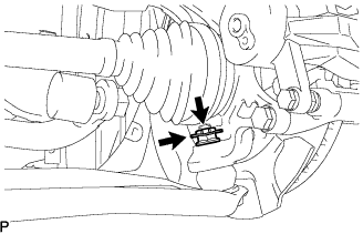
REMOVE FRONT AXLE SHAFT LH NUT (for TMC Made)
Using SST and a hammer, release the staked part of the axle hub nut.
SST
09930-00010
NOTICE:
Insert SST into the groove with the flat surface facing up.
Do not damage the tip of SST using grinders.
Completely unstake the staked part before removing the axle hub nut.
Do not damage the threads of the drive shaft.
Using a 30 mm socket wrench, remove the axle hub nut.
45.
REMOVE FRONT AXLE SHAFT LH NUT (for TMMF Made)
Using SST and a hammer, release the staked part of the axle hub nut.
SST
09930-00010
NOTICE:
Insert SST into the groove with the flat surface facing up.
Do not damage the tip of SST using grinders.
Completely unstake the staked part before removing the axle hub nut.
Do not damage the threads of the drive shaft.
Using a 30 mm socket wrench, remove the axle hub nut.
46.
REMOVE FRONT AXLE SHAFT RH NUT (for TMC Made)
HINT:
The removal procedure for the RH side is the same as that for the LH side.
47.
REMOVE FRONT AXLE HUB RH NUT (for TMMF Made)
HINT:
The removal procedure for the RH side is the same as that for the LH side.
48.
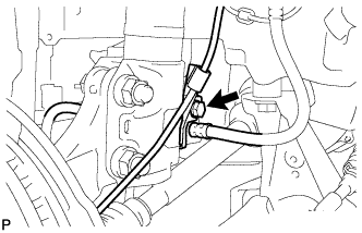
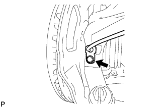
SEPARATE SPEED SENSOR FRONT LH (for TMC Made)
Remove the bolt and separate the speed sensor and flexible hose.
Remove the bolt and separate the speed sensor from the steering knuckle.
NOTICE:
Keep the speed sensor tip and installation portion free of foreign matter.
Remove the speed sensor without turning it from its original installation angle.
49.
SEPARATE SPEED SENSOR FRONT LH (for TMMF Made)
Remove the bolt and separate the speed sensor and flexible hose.
Remove the bolt and separate the speed sensor from the steering knuckle.
NOTICE:
Keep the speed sensor tip and installation portion free of foreign matter.
Remove the speed sensor without turning it from its original installation angle.
50.
SEPARATE SPEED SENSOR FRONT RH (for TMC Made)
HINT:
The removal procedure for the RH side is the same as that for the LH side.
51.
SEPARATE SPEED SENSOR FRONT RH (for TMMF Made)
HINT:
The removal procedure for the RH side is the same as that for the LH side.
52.
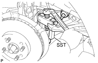
SEPARATE TIE ROD END SUB-ASSEMBLY LH (for TMC Made)
Remove the cotter pin and castle nut.
Using SST, separate the tie rod end from the steering knuckle.
SST
09628-62011
NOTICE:
Do not damage the tie rod end dust cover.
53.
SEPARATE TIE ROD END SUB-ASSEMBLY LH (for TMMF Made)
Remove the cotter pin and castle nut.
Using SST, separate the tie rod end from the steering knuckle.
SST
09628-62011
NOTICE:
Do not damage the tie rod end dust cover.
54.
SEPARATE TIE ROD END SUB-ASSEMBLY RH (for TMC Made)
HINT:
The removal procedure for the RH side is the same as that for the LH side.
55.
SEPARATE TIE ROD END SUB-ASSEMBLY RH (for TMMF Made)
HINT:
The removal procedure for the RH side is the same as that for the LH side.
56.
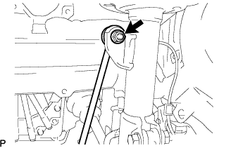
SEPARATE FRONT STABILIZER LINK ASSEMBLY LH (for TMC Made)
Remove the nut and separate the stabilizer link from the shock absorber.
HINT:
If the ball joint turns together with the nut, use a socket hexagon wrench 6 to hold the stud.
57.
SEPARATE FRONT STABILIZER LINK ASSEMBLY RH (for TMMF Made)
Remove the nut and separate the stabilizer link from the shock absorber.
HINT:
If the ball joint turns together with the nut, use a socket hexagon wrench 6 to hold the stud.
58.
SEPARATE FRONT STABILIZER LINK ASSEMBLY RH (for TMC Made)
HINT:
The removal procedure for the RH side is the same as that for the LH side.
59.
SEPARATE FRONT STABILIZER LINK ASSEMBLY RH (for TMMF Made)
HINT:
The removal procedure for the RH side is the same as that for the LH side.
60.
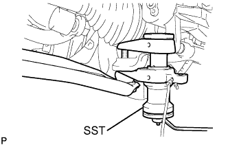
SEPARATE FRONT SUSPENSION ARM SUB-ASSEMBLY LOWER NO. 1 LH (for TMC Made)
Remove the clip and castle nut.
Using SST, separate the lower arm.
SST
09628-00011
NOTICE:
Do not damage the lower ball joint dust cover.
Suspend SST with a piece of string or the equivalent.
61.
SEPARATE FRONT SUSPENSION ARM SUB-ASSEMBLY LOWER NO. 1 LH (for TMMF Made)
Remove the clip and castle nut.
Using SST, separate the lower arm.
SST
09628-00011
NOTICE:
Do not damage the lower ball joint dust cover.
Suspend SST with a piece of string or the equivalent.
62.
SEPARATE FRONT SUSPENSION ARM SUB-ASSEMBLY LOWER NO. 1 RH (for TMC Made)
HINT:
The removal procedure for the RH side is the same as that for the LH side.
63.
SEPARATE FRONT SUSPENSION ARM SUB-ASSEMBLY LOWER NO. 1 RH (for TMMF Made)
HINT:
The removal procedure for the RH side is the same as that for the LH side.
64.
SEPARATE FRONT AXLE ASSEMBLY LH (for TMC Made)
Using a plastic hammer, tap the end of the drive shaft and disengage the fitting between the drive shaft and front axle.
HINT:
If it is difficult to disengage the fitting, tap the end of the drive shaft with a brass bar and hammer.
Push the front axle out of the vehicle to remove the drive shaft from the front axle.
NOTICE:
Do not push the front axle further out of the vehicle than is necessary.
Do not damage the outboard joint boot.
Do not damage the speed sensor rotor.
Suspend the drive shaft with a piece of string or the equivalent.
65.
SEPARATE FRONT AXLE ASSEMBLY LH (for TMMF Made)
Using a plastic hammer, tap the end of the drive shaft and disengage the fitting between the drive shaft and front axle.
HINT:
If it is difficult to disengage the fitting, tap the end of the drive shaft with a brass bar and hammer.
Push the front axle out of the vehicle to remove the drive shaft from the front axle.
NOTICE:
Do not push the front axle further out of the vehicle than is necessary.
Do not damage the outboard joint boot.
Do not damage the speed sensor rotor.
Suspend the drive shaft with a piece of string or the equivalent.
66.
SEPARATE FRONT AXLE ASSEMBLY RH (for TMC Made)
HINT:
The removal procedure for the RH side is the same as that for the LH side.
67.
SEPARATE FRONT AXLE ASSEMBLY RH (for TMMF Made)
HINT:
The removal procedure for the RH side is the same as that for the LH side.
68.
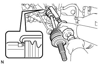
REMOVE FRONT DRIVE SHAFT ASSEMBLY LH (for TMC Made)
Using SST, remove the drive shaft.
SST
09520-01010
NOTICE:
Do not damage the oil seal.
Do not damage the inboard joint boot.
Do not drop the drive shaft.
69.
REMOVE FRONT DRIVE SHAFT ASSEMBLY LH (for TMMF Made)
Using SST, remove the drive shaft.
SST
09520-01010
NOTICE:
Do not damage the oil seal.
Do not damage the inboard joint boot.
Do not drop the drive shaft.
70.
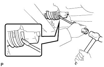
REMOVE FRONT DRIVE SHAFT ASSEMBLY RH (for TMC Made)
Using a screwdriver and hammer, remove the drive shaft.
NOTICE:
Do not damage the oil seal.
Do not damage the inboard joint boot.
Do not drop the drive shaft.
71.
REMOVE FRONT DRIVE SHAFT ASSEMBLY RH (for TMMF Made)
Using a screwdriver and hammer, remove the drive shaft.
NOTICE:
Do not damage the oil seal.
Do not damage the inboard joint boot.
Do not drop the drive shaft.
72.
REMOVE COLUMN HOLE COVER SILENCER SHEET
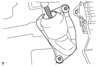
Remove the 2 clips and the column hole cover silencer sheet.
73.
SEPARATE STEERING INTERMEDIATE SHAFT ASSEMBLY NO. 2
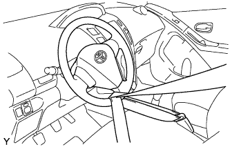
Hold the steering wheel with the seatbelt to avoid steering wheel rotation and damage to the spiral cable.
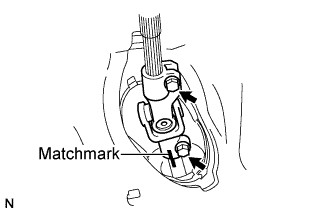
Put a matchmark on the sliding yoke and the intermediate shaft. Loosen the 2 bolts to separate the sliding yoke.
74.
REMOVE STEERING COLUMN HOLE COVER SUB-ASSEMBLY NO. 1
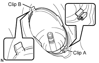
Remove clip A and separate the steering column hole cover from the body.
NOTICE:
Do not damage clip B.
75.
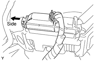
SEPARATE ECM
Move the pinch in the direction shown in the illustration and separate the connector.
76.
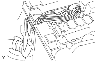
SEPARATE ENGINE WIRE
Remove the engine room relay block cover.
Disconnect the 2 connectors and disengage the wire harness clamp.
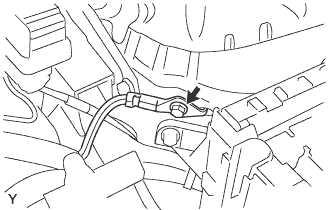
Remove the bolt and separate the earth wire. Check that the engine wire harness is disconnected between the body and engine
77.
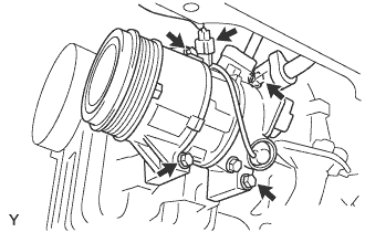
SEPARATE WITH PULLEY COMPRESSOR ASSEMBLY (w/ Air Conditioning System)
Disconnect the connector.
Remove the 4 bolts and separate the compressor.
HINT:
Secure the compressor and hoses off to the side instead of discharging the A/C system.
78.
REMOVE ENGINE ASSEMBLY WITH TRANSAXLE
Set the engine lifter under the engine assembly with transaxle.
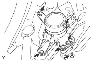
Remove the 5 bolts and the nut, then remove the engine mounting insulator RH.
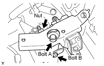
Remove bolt A from the engine mounting insulator LH. Remove bolt B and the nut, and separate the engine mounting insulator LH.
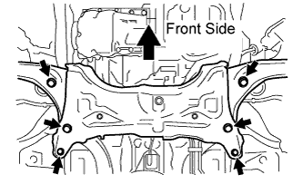
Remove the 6 bolts and the engine assembly with transaxle and front suspension member.
79.
SUPPORT ENGINE ASSEMBLY WITH TRANSAXLE
Remove the bolt and separate the wire harness clamp.
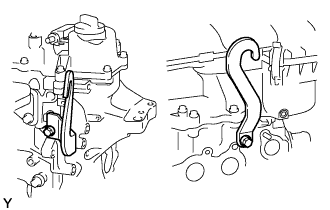
Install the engine hanger with the bolt.
Part No.:
No. 1 engine hanger:
12281 - 40030
No. 2 engine hanger:
12282 - 40010
Bolt:
91671 - 80820
Torque:
28 N*m{
286 kgf*cm
, 21 ft.*lbf
}
Attach the engine sling device to the engine hangers.
80.
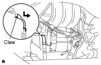
REMOVE FLYWHEEL HOUSING SIDE COVER (for 0.8 kW Type)
Disengage the claw while pushing it downward and remove the flywheel housing side cover.
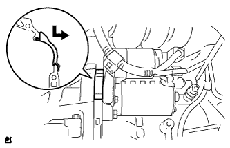
81.
REMOVE FLYWHEEL HOUSING SIDE COVER (for 0.9 kW Type)
Disengage the claw while pushing it downward and remove the flywheel housing side cover.
82.
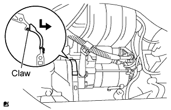
REMOVE FLYWHEEL HOUSING SIDE COVER (for 1.0 kW Type)
Disengage the claw while pushing it downward and remove the flywheel housing side cover.
83.
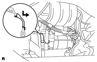
REMOVE FLYWHEEL HOUSING SIDE COVER (for 1.3 kW Type)
Disengage the claw while pushing it downward and remove the flywheel housing side cover.
84.
REMOVE STARTER ASSEMBLY (for 0.8 kW Type)
Separate the harness clamp.
Remove the bolt and remove the wire harness bracket.
Remove the terminal cap. Separate the harness clamp.
Remove the nut and disconnect terminal 30.
Disconnect the connector.
Remove the 2 bolts and remove the starter assembly.
85.
REMOVE STARTER ASSEMBLY (for 0.9 kW Type)
86.
REMOVE STARTER ASSEMBLY (for 1.0 kW Type)
Separate the harness clamp.
Remove the bolt and remove the wire harness bracket.
Remove the terminal cap. Separate the harness clamp.
Remove the nut and disconnect terminal 30.
Disconnect the connector.
Remove the 2 bolts and remove the starter assembly.
87.
REMOVE STARTER ASSEMBLY (for 1.3 kW Type)
88.
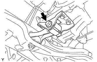
SEPARATE ENGINE MOVING CONTROL ROD
Remove the bolt and separate the engine moving control rod.
89.
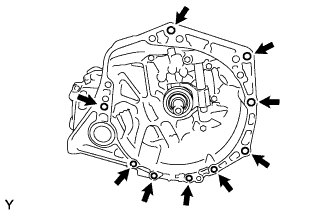
REMOVE MULTI-MODE MANUAL TRANSAXLE ASSEMBLY (for Multi-Mode Manual Transaxle)
Remove the 9 bolts and the multi-mode manual transaxle.
90.
REMOVE MANUAL TRANSAXLE ASSEMBLY (for Manual Transaxle)
Remove the 9 bolts and manual transaxle.
91.
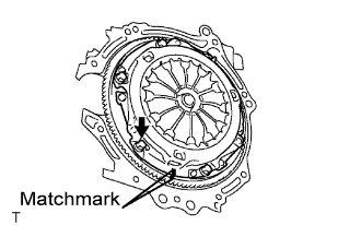
REMOVE CLUTCH COVER ASSEMBLY (for Multi-Mode Manual Transaxle)
Place matchmarks on the flywheel and clutch cover.
Loosen each set bolt one turn at a time until the spring tension is released.
Remove the 6 bolts, and pull off the clutch cover with the clutch disc.
NOTICE:
Do not drop the clutch disc.
When replacing the clutch disc, be sure to replace it together with the clutch cover as a set.
92.
REMOVE CLUTCH COVER ASSEMBLY (for Manual Transaxle)
Align the matchmark on the clutch cover with the one on the flywheel.
Loosen each set bolt by one turn at a time until the spring tension is released.
Remove the set bolts and the clutch cover.
NOTICE:
Do not drop the clutch disc.
93.
REMOVE CLUTCH DISC ASSEMBLY (for Manual Transaxle)
NOTICE:
Keep the lining part of the clutch disk and the surfaces of the pressure plate and flywheel free of oil and foreign matter.
94.
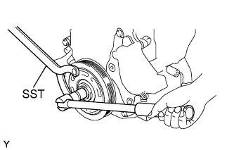
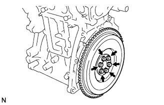
REMOVE FLYWHEEL ASSEMBLY
Hold the crankshaft pulley with SST.
SST
09960-10010
(09962-01000, 09963-01000)
Remove the 6 bolts and the flywheel.
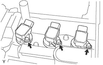
95.
REMOVE IGNITION COIL NO. 1
Disconnect the 3 connectors.
Remove the 3 bolts and 3 ignition coils.
96.
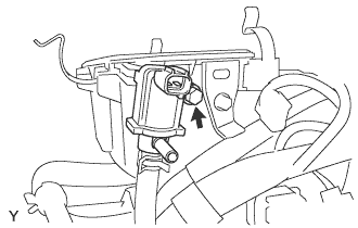
REMOVE DUTY VACUUM SWITCHING VALVE
Disconnect the connector.
Remove the bolt and the duty vacuum switching valve.
97.
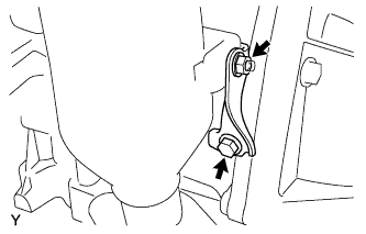
REMOVE MANIFOLD STAY
Remove the bolt and nut, and remove the manifold stay.
98.
REMOVE EXHAUST MANIFOLD ASSEMBLY
Remove the 2 bolts and 2 nuts.
Remove the exhaust manifold and gasket.
99.
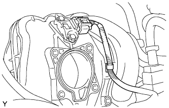
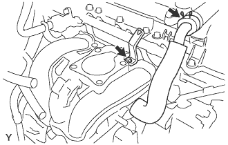
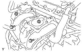
REMOVE THROTTLE WITH MOTOR BODY ASSEMBLY
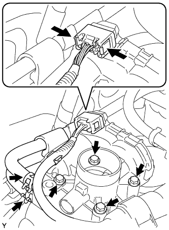
Pinch the connector as illustrated, then disconnect the connector.
Disconnect the 2 water by-pass hoses.
Remove the 4 bolts and the throttle body.
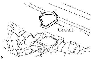
Remove the throttle body gasket.
100.
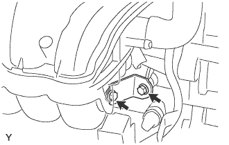
REMOVE INTAKE MANIFOLD STAY
Remove the 2 bolts and the intake manifold stay.
101.
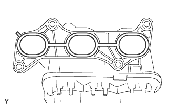
REMOVE INTAKE MANIFOLD
Disconnect the manifold absolute pressure sensor connector.
Separate the wire harness.
Remove the bolt and wire harness clamp. Disconnect the ventilation hose.
Remove the 2 bolts and 2 nuts.
Remove the intake manifold and gasket.
102.
REMOVE FUEL DELIVERY PIPE
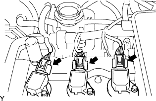
Disconnect the 3 ignition coil connectors.
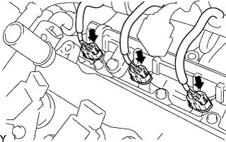
Disconnect the 3 injector connectors.
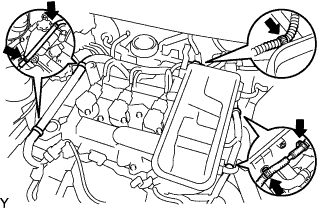
Disengage the 5 clamps, and separate the engine wire harness from the cylinder head cover.
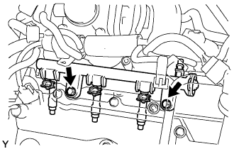
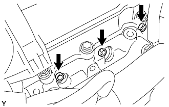
Remove the 2 bolts and delivery pipe together with the 3 injectors.
NOTICE:
Do not drop the injectors when removing the delivery pipe.
Remove the 3 injector vibration insulators from the cylinder head.
103.
REMOVE FUEL INJECTOR ASSEMBLY
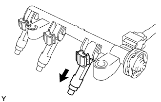
Pull the 3 injectors out of the fuel delivery pipe.
104.
REMOVE RADIO SETTING CONDENSER
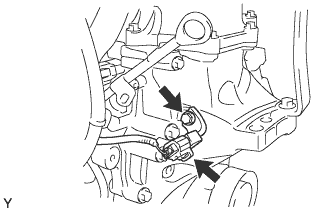
Disconnect the connector.
Remove the bolt and radio setting condenser.
105.
REMOVE KNOCK SENSOR
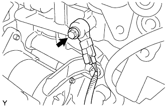
Disconnect the connector.
Remove the bolt and knock sensor.
106.
REMOVE ENGINE WIRE
Remove the bolt and separate the engine wire harness.
Separate the wire harness clamps and remove the engine wire.
107.
REMOVE HEATER WATER OUTLET HOSE A(FROM HEATER UNIT)
108.
REMOVE HEATER WATER INLET HOSE A
109.
REMOVE RADIATOR HOSE NO. 1
110.
REMOVE RADIATOR HOSE NO. 2