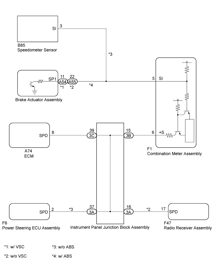
METER / GAUGE SYSTEM > Speed Signal Circuit |
| 1.INSPECT COMBINATION METER ASSEMBLY (INPUT VOLTAGE) |
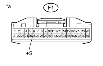 |
Disconnect the F1 combination meter assembly connector.
Measure the voltage according to the value(s) in the table below.
| Tester Connection | Switch Condition | Specified Condition |
| F1-6 (+S) - Body ground | Ignition switch ON | 4.5 to 14 V |
| *a | Front view of wire harness connector (to Combination Meter Assembly) |
Reconnect the combination meter assembly connector.
|
| ||||
| OK | |
 |
| 2.SYSTEM CHECK |
Check the vehicle specifications.
| Result | Proceed to |
| w/ ABS | A |
| w/o ABS | B |
|
| ||||
| A | |
|
| 3.INSPECT COMBINATION METER ASSEMBLY (OUTPUT VOLTAGE) |
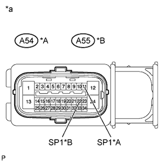 |
Disconnect the A54*1, A55*2 brake actuator assembly connector.
Measure the voltage according to the value(s) in the table below.
| Tester Connection | Switch Condition | Specified Condition |
| A54-11 (SP1)*1 - Body ground | Ignition switch ON | 11 to 14 V |
| A55-22 (SP1)*2 - Body ground | Ignition switch ON | 11 to 14 V |
| *A | w/ VSC |
| *B | w/o VSC |
| *a | Front view of wire harness connector (to Brake Actuator Assembly) |
Reconnect the brake actuator assembly connector.
|
| ||||
| OK | |
|
| 4.INSPECT COMBINATION METER ASSEMBLY (INPUT WAVEFORM) |
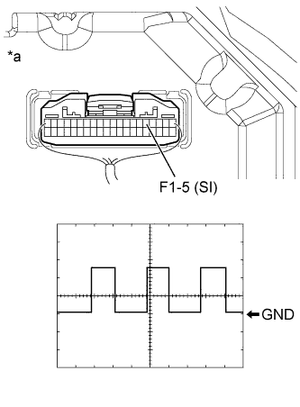 |
Check the input waveform.
Remove the combination meter assembly with the connector(s) still connected.
Connect an oscilloscope to terminal F1-5 (SI) and body ground.
Turn the ignition switch to ON.
Turn the wheel slowly.
Check the signal waveform according to the condition(s) in the table below.
| Item | Condition |
| Tool setting | 5 V/DIV., 20 ms./DIV. |
| Vehicle condition | Driving at approximately 20 km/h (12 mph) |
| *a | Component with harness connected (Combination Meter Assembly) |
| Result | Proceed to |
| OK | A |
| NG (for LHD) | B |
| NG (for RHD) | C |
|
| ||||
|
| ||||
| A | ||
 | ||
| ||
| 5.INSPECT COMBINATION METER ASSEMBLY (OUTPUT VOLTAGE) |
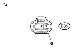 |
Disconnect the B85 speedometer sensor connector.
Measure the voltage according to the value(s) in the table below.
| Tester Connection | Switch Condition | Specified Condition |
| B85-3 (SI) - Body ground | Ignition switch ON | 11 to 14 V |
| *a | Front view of wire harness connector (to Speedometer Sensor) |
Reconnect the speedometer sensor connector.
|
| ||||
| OK | |
|
| 6.INSPECT COMBINATION METER ASSEMBLY (INPUT WAVEFORM) |
|
Check the input waveform.
Remove the combination meter assembly with the connector(s) still connected.
Connect an oscilloscope to terminal F1-5 (SI) and body ground.
Turn the ignition switch to ON.
Turn the wheel slowly.
Check the signal waveform according to the condition(s) in the table below.
| Item | Condition |
| Tool setting | 5 V/DIV., 20 ms./DIV. |
| Vehicle condition | Driving at approximately 20 km/h (12 mph) |
| *a | Component with harness connected (Combination Meter Assembly) |
|
| ||||
| OK | ||
| ||
| ||
| 7.CHECK HARNESS AND CONNECTOR (COMBINATION METER ASSEMBLY - BRAKE ACTUATOR ASSEMBLY) |
Disconnect the F1 combination meter assembly connector.
Disconnect the A54*1, A55*2 brake actuator assembly connector.
Measure the resistance according to the value(s) in the table below.
| Tester Connection | Condition | Specified Condition |
| A54-11 (SP1)*1 - F1-5 (SI) | Always | Below 1 Ω |
| A55-22 (SP1)*2 - F1-5 (SI) | Always | Below 1 Ω |
| A54-11 (SP1)*1 - Body ground | Always | 10 kΩ or higher |
| A55-22 (SP1)*2 - Body ground | Always | 10 kΩ or higher |
|
| ||||
| OK | ||
| ||
| ||
| 8.CHECK HARNESS AND CONNECTOR (COMBINATION METER ASSEMBLY - SPEEDOMETER SENSOR) |
Disconnect the F1 combination meter assembly connector.
Disconnect the B85 speedometer sensor connector.
Measure the resistance according to the value(s) in the table below.
| Tester Connection | Condition | Specified Condition |
| B85-3 (SI) - F1-5 (SI) | Always | Below 1 Ω |
| B85-3 (SI) - Body ground | Always | 10 kΩ or higher |
|
| ||||
| OK | ||
| ||
| ||
| 9.CHECK HARNESS AND CONNECTOR (COMBINATION METER ASSEMBLY - INSTRUMENT PANEL JUNCTION BLOCK ASSEMBLY) |
Disconnect the 3B instrument panel junction block assembly connector.
Disconnect the F1 combination meter assembly connector.
Measure the resistance according to the value(s) in the table below.
| Tester Connection | Condition | Specified Condition |
| F1-6 (+S) - 3B-15 | Always | Below 1 Ω |
| F1-6 (+S) - Body ground | Always | 10 kΩ or higher |
Reconnect the instrument panel junction block assembly connector.
Reconnect the combination meter assembly connector.
|
| ||||
| OK | |
|
| 10.INSPECT ECM |
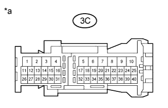 |
Disconnect the 3C instrument panel junction block assembly connector.
Measure the voltage according to the value(s) in the table below.
| Tester Connection | Switch Condition | Specified Condition |
| 3C-39 - Body ground | Ignition switch ON | 4.5 to 14 V |
| *a | Front view of wire harness connector (to Instrument Panel Junction Block Assembly) |
Reconnect the instrument panel junction block assembly connector.
|
| ||||
| OK | |
|
| 11.SYSTEM CHECK |
Check the vehicle specifications.
| Result | Proceed to |
| w/o VSC | A |
| w/o ABS | B |
|
| ||||
| A | |
|
| 12.INSPECT RADIO RECEIVER ASSEMBLY |
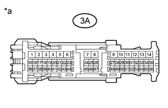 |
Disconnect the 3A instrument panel junction block assembly connector.
Measure the voltage according to the value(s) in the table below.
| Tester Connection | Switch Condition | Specified Condition |
| 3A-16 - Body ground | Ignition switch ON | 4.5 to 14 V |
| *a | Front view of wire harness connector (to Instrument Panel Junction Block Assembly) |
|
| ||||
| OK | ||
| ||
| ||
| 13.INSPECT POWER STEERING ECU ASSEMBLY |
|
Disconnect the 3A instrument panel junction block assembly connector.
Measure the voltage according to the value(s) in the table below.
| Tester Connection | Switch Condition | Specified Condition |
| 3A-37 - Body ground | Ignition switch ON | 4.5 to 14 V |
| *a | Front view of wire harness connector (to Instrument Panel Junction Block Assembly) |
Reconnect the instrument panel junction block assembly connector.
|
| ||||
| OK | ||
| ||
| ||
| 14.CHECK HARNESS AND CONNECTOR (INSTRUMENT PANEL JUNCTION BLOCK ASSEMBLY - ECM) |
Disconnect the 3C instrument panel junction block assembly connector.
Disconnect the A74 ECM connector.
Measure the resistance according to the value(s) in the table below.
| Tester Connection | Condition | Specified Condition |
| 3C-39 - A74-8 (SPD) | Always | Below 1 Ω |
| 3C-39 - Body ground | Always | 10 kΩ or higher |
| Result | Proceed to |
| NG | A |
| OK (for 1NZ-FE) | B |
| OK (for 2NZ-FE) | C |
Reconnect the instrument panel junction block assembly connector.
Reconnect the ECM connector.
|
| ||||
|
| ||||
| A | ||
| ||
| ||
| 15.CHECK HARNESS AND CONNECTOR (INSTRUMENT PANEL JUNCTION BLOCK ASSEMBLY - RADIO RECEIVER ASSEMBLY) |
Disconnect the 3A instrument panel junction block assembly connector.
Disconnect the F47 radio receiver assembly connector.
Measure the resistance according to the value(s) in the table below.
| Tester Connection | Condition | Specified Condition |
| 3A-16 - F47-17 (SPD) | Always | Below 1 Ω |
| 3A-16 - Body ground | Always | 10 kΩ or higher |
Reconnect the instrument panel junction block assembly connector.
Reconnect the radio receiver assembly connector.
|
| ||||
| OK | ||
| ||
| ||
| 16.CHECK HARNESS AND CONNECTOR (INSTRUMENT PANEL JUNCTION BLOCK ASSEMBLY - POWER STEERING ECU ASSEMBLY) |
Disconnect the 3A instrument panel junction block assembly connector.
Disconnect the F6 power steering ECU assembly connector.
Measure the resistance according to the value(s) in the table below.
| Tester Connection | Condition | Specified Condition |
| 3A-37 - F6-2 (SPD) | Always | Below 1 Ω |
| 3A-37 - Body ground | Always | 10 kΩ or higher |
| Result | Proceed to |
| NG | A |
| OK (for LHD) | B |
| OK (for RHD) | C |
Reconnect the instrument panel junction block assembly connector.
Reconnect the power steering ECU assembly connector.
|
| ||||
|
| ||||
| A | ||
| ||
| ||

