CRANKSHAFT
REMOVAL
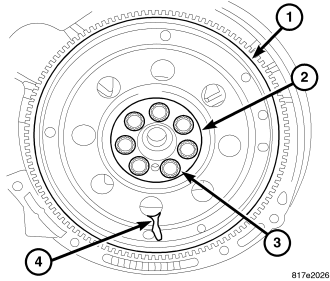
NOTE: Crankshaft can not be removed when engine is in vehicle.
1. Remove engine assembly from vehicle (Refer to 9 - ENGINE - REMOVAL).
2. Separate transaxle from engine.
3. Remove flex plate/flywheel (1).
4. Remove crankshaft rear oil seal (Refer to 9 - ENGINE/ENGINE BLOCK/CRANKSHAFT OIL SEAL - REAR - REMOVAL).
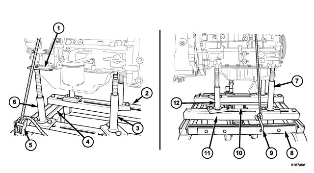
5. Remove engine from cradle 6710 (11) and mount engine on a suitable repair stand.
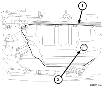
6. Drain engine oil (2).
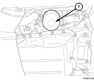
7. Remove oil filter (1).
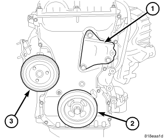
8. Remove crankshaft vibration damper (2) (Refer to 9 - ENGINE/ENGINE BLOCK/VIBRATION DAMPER - REMOVAL).
9. Remove water pump pulley (3).
10. Remove engine mount support bracket (1).
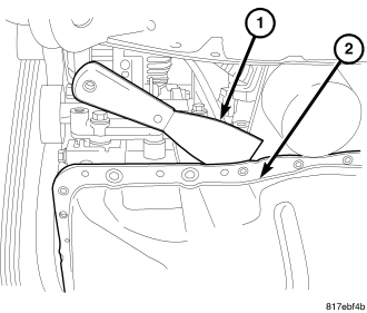
11. Remove the oil pan (2) (Refer to 9 - ENGINE/LUBRICATION/OIL PAN - REMOVAL).
12. Remove timing chain cover (Refer to 9 - ENGINE/VALVE TIMING/TIMING BELT / CHAIN COVER(S) - REMOVAL).
13. Remove the timing chain (Refer to 9 - ENGINE/VALVE TIMING/TIMING BELT/CHAIN AND SPROCKETS - REMOVAL).
14. Remove balance shaft module.
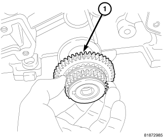
15. Remove the crankshaft sprocket (1).
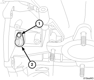
16. Remove crankshaft position sensor retaining bolt (1) and remove sensor (2).
17. Remove ladder frame (Refer to 9 - ENGINE/ENGINE BLOCK/LADDER FRAME - REMOVAL).
NOTE: If piston/connecting rod replacement is necessary, remove cylinder head (Refer to 9 - ENGINE/CYLINDER HEAD - REMOVAL).
CAUTION: DO NOT use a number stamp or a punch to mark connecting rods. Damage to connecting rod could occur.
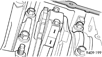
18. Using a permanent ink or paint marker, identify cylinder number on each connecting rod and cap.
19. Remove all connecting rod bolts and caps. Care should be taken not to damage the fracture rod and cap surfaces.
NOTE: Do not reuse connecting rod bolts.
20. Remove main bearing caps.
CAUTION: Use extreme care when handling crankshaft. Tone wheel damage can occur if crankshaft is mis-handled.
21. Lift out crankshaft from cylinder block. Do not damage the main bearings or journals when removing the crankshaft.
INSPECTION
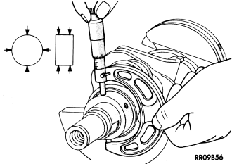
The crankshaft main journals should be checked for excessive wear, taper and scoring. Limits of taper on any crankshaft main journals should be held to 0.006 mm (0.00024 in.). Limits of taper on any crankshaft rod journals should be held to 0.005 mm (0.0002 in.). DO NOT nick crank pin or bearing fillets. Limits of out of round on any crankshaft journals should be held to 0.005 mm (0.0002 in). DO NOT nick crank pin or bearing fillets.
INSTALLATION
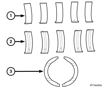
The crankshaft is supported in five main bearings. All upper bearing shells (2) in the crankcase have oil grooves and holes. All lower bearing shells (1) are smooth. Crankshaft end play is controlled by a two piece thrust bearing (3) on the number three main bearing journal.
1. Clean main bearing cap bolt holes with Mopar® brake parts cleaner or equivalent and blow out with compressed air.
2. Install the main bearing upper (2) shells with the lubrication groove and oil hole in the engine block.
3. Make certain oil holes in block line up with oil hole in bearings and bearing tabs seat in the block tab slots.
NOTE: If the crankshaft is sent out for machine work, it must be balanced as an assembly with the target ring installed.
4. Clean crankshaft and target ring with MOPAR® Brake Parts cleaner and dry with compressed air to ensure that the crankshaft mating surface and target ring mounting holes are free from oil and lock patch debris.
NOTE: Always use NEW mounting screws whether installing original or new target ring.
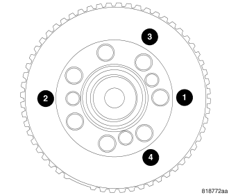
5. Install NEW mounting screws finger tight starting with the #1 location. Make sure engagement occurs with the shoulder of the screws and mounting hole before starting all other screws.
6. Tighten all mounting screws with T30 torx bit to 13 N·m (110 in-lbs) in the sequence shown.
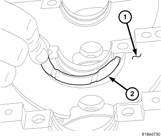
NOTE: Lightly apply trans gel to thrust bearings to hold bearings in block.
NOTE: The thrust bearings must be installed the notches facing the crankshaft.
7. Install thrust bearings (2) in block (1).
CAUTION: Do not get oil on the ladder frame mating surface. It will affect the ability of the RTV to seal the ladder frame to cylinder block.
8. Oil the bearings and journals. Install crankshaft in engine block.
9. Install lower main bearings (1) into main bearing cap. Make certain the bearing tabs are seated into the bearing cap slots.
NOTE: Main bearing caps are stamped 1 - 5 front to rear. Arrows on the caps must point towards the front of the engine.
10. Install main bearing caps to engine block.
11. Before installing the bolts the threads should be clean and dry.
12. To ensure correct thrust bearing alignment, perform the following steps:
- Step 1: Rotate crankshaft until number 4 piston is at TDC.
- Step 2: Move crankshaft rearward to limits of travel.
- Step 3: Then, move crankshaft forward to limits of travel.
- Step 4: Wedge an appropriate tool between the rear of the cylinder block and the rear crankshaft counterweight. This will hold the crankshaft in its furthest forward position.
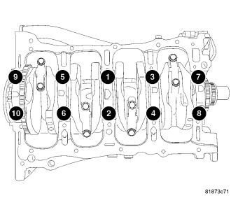
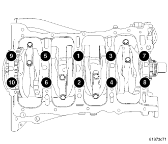
13. Tighten bolts (1-10) to 27 N·m + 45° (20 ft. lbs. + 45°) in the sequence shown above.
14. Remove wedge tool used to hold crankshaft.
15. Check the crankshaft turning torque, it should not exceed 5.6 N·m (50 in. lbs.).
16. Check crankshaft end play (Refer to 9 - ENGINE/ENGINE BLOCK/CRANKSHAFT - STANDARD PROCEDURE).
17. Install connecting rod bearings and caps. Do Not Reuse Connecting Rod Bolts. Tighten connecting rod bolts to 20 N·m + 90° (15 ft. lbs.) + 90° (Refer to 9 - ENGINE/ENGINE BLOCK/PISTON & CONNECTING ROD - INSTALLATION).
18. Install the ladder frame assembly (Refer to 9 - ENGINE/ENGINE BLOCK/LADDER FRAME - INSTALLATION).
19. Install the balance shaft module (Refer to 9 - ENGINE/LUBRICATION/OIL PUMP - INSTALLATION).
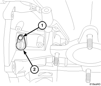
20. Install crankshaft position sensor (2) and tighten bolt (1).
21. Install cylinder head if it was removed (Refer to 9 - ENGINE/CYLINDER HEAD - INSTALLATION).
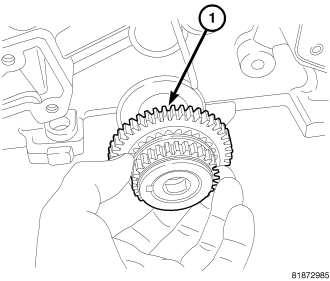
22. Install front crankshaft sprocket (1).
23. Install the timing chain (Refer to 9 - ENGINE/VALVE TIMING/TIMING BELT/CHAIN AND SPROCKETS - INSTALLATION).
24. Install the timing chain front cover (Refer to 9 - ENGINE/VALVE TIMING/TIMING BELT / CHAIN COVER(S) - INSTALLATION).
25. Install the oil pan (Refer to 9 - ENGINE/LUBRICATION/OIL PAN - INSTALLATION).
26. Install rear crankshaft oil seal (Refer to 9 - ENGINE/ENGINE BLOCK/CRANKSHAFT OIL SEAL - REAR - INSTALLATION).
27. Install front crankshaft oil seal (Refer to 9 - ENGINE/ENGINE BLOCK/CRANKSHAFT OIL SEAL - FRONT - INSTALLATION).
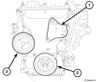
28. Install engine mount support bracket (1).
29. Install crankshaft vibration damper (2) (Refer to 9 - ENGINE/ENGINE BLOCK/VIBRATION DAMPER - INSTALLATION).
30. Install water pump pulley (3).
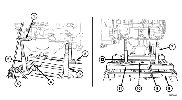
31. Remove engine from repair stand and position on dolly 6135 (8) and engine support cradle 6710 (2,11). Install safety straps (5, 9) around the engine to cradle and tighten and lock them into position.
32. Install crankshaft rear oil seal (Refer to 9 - ENGINE/ENGINE BLOCK/CRANKSHAFT OIL SEAL - REAR - INSTALLATION).
33. Install drive plate/flex plate using new bolts. Tighten bolts to 95 N·m (70 ft. lbs.).
34. Attach transaxle to engine. Tighten bellhousing bolts to 101 N·m (75 ft. lbs.).
35. Install the engine assembly (Refer to 9 - ENGINE - INSTALLATION).
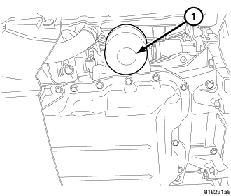
36. Install new oil filter (1) and fill with oil.
37. Fill with coolant (Refer to 7 - COOLING - STANDARD PROCEDURE).
38. Start engine and check for leaks.
39. Install engine cover.