REMOVAL
AIR INLET HOUSING
WARNING: Refer to the applicable warnings and cautions for this system before performing the following operation (Refer to 24 - HEATING & AIR CONDITIONING/PLUMBING - WARNINGS) and (Refer to 24 - HEATING & AIR CONDITIONING/PLUMBING - CAUTIONS). Failure to follow the warnings and cautions could result in possible personal injury or death.
WARNING: On vehicles equipped with airbags, disable the airbag system before attempting any steering wheel, steering column, or instrument panel component diagnosis or service. Disconnect and isolate the negative battery (ground) cable, then wait two minutes for the airbag system capacitor to discharge before performing further diagnosis or service. This is the only sure way to disable the airbag system. Failure to take the proper precautions could result in accidental airbag deployment and possible personal injury or death.
NOTE: The air inlet housing must be removed from HVAC housing and disassembled for service of the recirculation-air door.
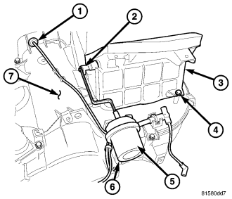
1. Disconnect and isolate the negative battery cable.
2. Remove the HVAC housing (7) and place it on a workbench (refer to 24 - HEATING & AIR CONDITIONING/DISTRIBUTION/HOUSING-HVAC - REMOVAL).
3. Disconnect the HVAC vacuum harness connector (6) from the recirculation door actuator (5) and if required, position the vacuum harness (1) out of the way.
4. Carefully disconnect the recirculation door actuator from the recirculation door lever (2) and if required, remove the actuator from the HVAC housing (refer to 24 - HEATING & AIR CONDITIONING/CONTROLS/ACTUATOR-RECIRCULATION DOOR - REMOVAL).
5. Remove the four screws (4) that secure the air inlet housing (3) to the top of the HVAC housing and remove the air inlet housing.
NOTE: If the foam seal on the air inlet housing is deformed or damaged, it must be replaced.
6. If required, disassemble the air inlet housing (refer to 24 - HEATING & AIR CONDITIONING/DISTRIBUTION/HOUSING-HVAC - HOUSING-AIR INLET - DISASSEMBLY).
HVAC HOUSING
WARNING: Refer to the applicable warnings and cautions for this system before performing the following operation (refer to 24 - HEATING & AIR CONDITIONING/PLUMBING - WARNING) and (refer to 24 - HEATING & AIR CONDITIONING/PLUMBING - CAUTION). Failure to follow the warnings and cautions could result in possible personal injury or death.
WARNING: On vehicles equipped with airbags, disable the airbag system before attempting any steering wheel, steering column, or instrument panel component diagnosis or service. Disconnect and isolate the battery negative (ground) cable, then wait two minutes for the airbag system capacitor to discharge before performing further diagnosis or service. This is the only sure way to disable the airbag system. Failure to take the proper precautions could result in an accidental airbag deployment and possible personal injury or death.
NOTE: The HVAC housing must be removed from the vehicle and disassembled for service of the A/C evaporator and the mode-air and blend-air doors.
NOTE: LHD model shown in illustrations. RHD model similar.
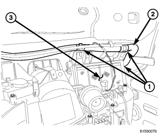
1. Disconnect and isolate the negative battery cable.
2. Recover the refrigerant from the refrigerant system (refer to 24 - HEATING & AIR CONDITIONING/PLUMBING - STANDARD PROCEDURE - REFRIGERANT SYSTEM RECOVERY).
3. Drain the engine cooling system (refer to 7 - COOLING - STANDARD PROCEDURE - COOLING SYSTEM DRAIN).
4. Remove the instrument panel from the passenger compartment (refer to 23 - BODY/INSTRUMENT PANEL ASSEMBLY - REMOVAL).
5. Disengage the three retaining straps (1) that secure the dash panel wire harness (2) to the top of the HVAC air inlet housing (3) and position the wire harness out of the way.
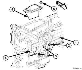
6. Remove the two nuts that secure the A/C accumulator to the dash panel and disconnect the refrigerant lines from the A/C evaporator (refer to 24 - HEATING & AIR CONDITIONING/PLUMBING/ACCUMULATOR-A/C - REMOVAL) and (refer to 24 - HEATING & AIR CONDITIONING/PLUMBING/LINE-A/C LIQUID - REMOVAL).
7. Install plugs into or caps over the opened refrigerant line fittings and evaporator ports
8. Disconnect the heater hoses from the heater core tubes and install plugs into or caps over the heater core tubes.
9. Disconnect the HVAC system vacuum supply line from the engine vacuum harness at the connector located near the evaporator tapping block.
10. Remove the condensation drain tube (refer to 24 - HEATING & AIR CONDITIONING/PLUMBING/TUBE-CONDENSATION DRAIN - REMOVAL).
11. Remove the one nut (2) that secures the HVAC housing (4) to the engine compartment side of the dash panel (1).
12. Remove the two nuts (3) that secure the HVAC housing to the passenger compartment side of the dash panel.
13. Pull the HVAC housing assembly rearward so that the mounting studs and condensate drain clear the dash panel and remove the HVAC housing from the passenger compartment.
14. If required, remove the fresh air inlet screen (5) from the top of the dash panel (refer to 24 - HEATING & AIR CONDITIONING/DISTRIBUTION/HOUSING-HVAC - SCREEN-AIR INLET - REMOVAL).
FRESH AIR INLET SCREEN
CAUTION: Replacement of the fresh air inlet screen is required once the screen is removed from the dash panel. Failure to follow this caution can result in a water leak within the vehicle and possible damage to the blower motor and resistor.
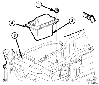
NOTE: LHD model shown. RHD model similar.
1. Remove the wiper arms (refer to 8 - ELECTRICAL/WIPERS/WASHERS/ARMS-WIPER - REMOVAL).
2. Remove the cowl grille from the top of the dash panel in the engine compartment (refer to 23 - BODY/EXTERIOR/GRILLE-COWL - REMOVAL).
NOTE: Make sure that no foreign material or debris is present on the top of the dash panel in the engine compartment which could possibly block or restrict air flow through the fresh air inlet screen or cause rustling type noises when the blower motor is operated. Use a vacuum to remove any foreign material or debris as necessary.
3. Remove the two nuts (1) that secure the inboard side of the fresh air inlet screen (2) to the dash panel (3).
4. Pull the inboard side of the fresh air inlet screen upward to disengage the two retaining tabs (4) that secure the outboard side of the air inlet screen to the to the dash panel and remove and discard the screen.