| Last Modified: 11-27-2007 | 1.6 A | |
| Service Category: Engine/Hybrid System | Section: Cooling | |
| Model Year: 2008 | Model: LX570 | Doc ID: RM000002S4R00HX |
| Title: 3UR-FE COOLING: WATER PUMP: INSTALLATION (2008 LX570) | ||
INSTALLATION
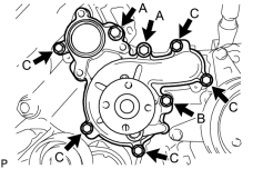
1. INSTALL WATER PUMP ASSEMBLY
|
(a) Install a new gasket and the water pump with the 8 bolts shown in the illustration. Torque: 47 N·m (479 kgf·cm, 35 ft·lbf) Torque: 23 N·m (235 kgf·cm, 17 ft·lbf) Torque: 20 N·m (204 kgf·cm, 15 ft·lbf) Standard Bolt:
|
2. INSTALL WATER PUMP PULLEY
|
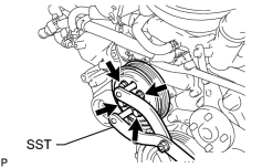
(a) Temporarily install the pulley with the 4 bolts. |
(b) Using SST, hold the pulley and tighten the 4 bolts.
SST: 09960-10010
09962-01000
09963-01000
Torque: 21 N·m (214 kgf·cm, 15 ft·lbf)
3. INSTALL WATER INLET HOUSING
(a) Install a new gasket to the water pump.
|
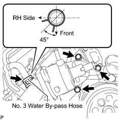
(b) Install the water inlet housing with the 3 bolts and connect the No. 3 water by-pass hose. Torque: 21 N·m (214 kgf·cm, 15 ft·lbf) HINT:
Install the hose so that the direction of the hose clamp is as indicated in the illustration. |
|
(c) Install the air tube bracket bolt. Torque: 10 N·m (102 kgf·cm, 7 ft·lbf) |
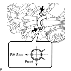
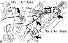
(d) Connect the No. 5 water by-pass hose.
HINT:
Install the hose so that the direction of the hose clamp is as indicated in the illustration.
|
(e) Connect the air pump connector clamp holder. |
(f) Attach the wire harness clamp.
(g) Connect the air pump connector.
(h) Connect the No. 2 and No. 3 air hoses.
4. CONNECT NO. 2 WATER BY-PASS PIPE SUB-ASSEMBLY (w/ Oil Cooler)
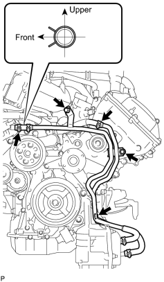
(a) Connect the water by-pass pipe with water hose.
HINT:
Install the hose so that the direction of the hose clamp is as indicated in the illustration.
(b) Install the 3 bolts.
Torque: 10 N·m (102 kgf·cm, 7 ft·lbf)
(c) Connect the No. 6 water by-pass hose.
5. INSTALL NO. 1 WATER BY-PASS HOSE

6. INSTALL FAN SHROUD
7. INSTALL NO. 1 RADIATOR HOSE
8. INSTALL NO. 2 RADIATOR HOSE
9. INSTALL AIR CLEANER ASSEMBLY
10. INSTALL AIR CLEANER HOSE ASSEMBLY
11. ADD ENGINE COOLANT
12. INSPECT FOR COOLANT LEAK
13. INSTALL UPPER RADIATOR SUPPORT SEAL
14. INSTALL ENGINE ROOM SIDE COVER RH
15. INSTALL ENGINE ROOM SIDE COVER LH
16. INSTALL V-BANK COVER SUB-ASSEMBLY
17. INSTALL NO. 1 ENGINE UNDER COVER SUB-ASSEMBLY
18. INSTALL FRONT FENDER SPLASH SHIELD SUB-ASSEMBLY LH
19. INSTALL FRONT FENDER SPLASH SHIELD SUB-ASSEMBLY RH

|

|