| Last Modified: 11-27-2007 | 1.6 A | |
| Service Category: Engine/Hybrid System | Section: Lubrication | |
| Model Year: 2008 | Model: LX570 | Doc ID: RM000002S4U00FX |
| Title: 3UR-FE LUBRICATION: OIL PUMP: INSTALLATION (2008 LX570) | ||
INSTALLATION
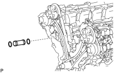
1. INSTALL WATER INLET PIPE
|
(a) Apply soapy water to 2 new O-rings and install them to the inlet pipe. |
(b) Install the inlet pipe to the No. 1 heat exchanger cover.
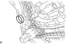
2. INSTALL TIMING CHAIN COVER SUB-ASSEMBLY
|
(a) Apply a light coat of engine oil to a new oil pump gasket. |
(b) Install the oil pump gasket.
|
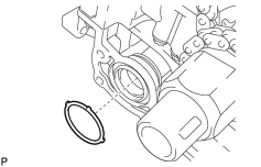
(c) Apply a light coat of engine oil to a new O-ring. |
(d) Install the O-ring.
(e) Apply seal packing in a continuous line to the timing chain cover as shown in the following illustration.
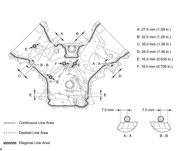
Seal packing:
Toyota Genuine Seal Packing Black, Three Bond 1207B or equivalent
Apply seal packing as follows:
|
Area |
Seal Packing Diameter |
Application Position from Inside Edge of Cover |
|---|---|---|
|
Continuous Line Area |
3.0 to 4.0 mm (0.118 to 0.157 in.) |
2.5 mm (0.0984 in.) |
|
Dashed Line Area |
6.4 mm (0.252 in.) or more, or within OK area shown in illustration |
7.0 mm (0.276 in.) |
|
Diagonal Line Area |
3.0 to 4.0 mm (0.118 to 0.157 in.) |
5.5 mm (0.217 in.) |
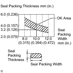
NOTICE:
- When the contact surfaces are wet, wipe them with an oil-free cloth before applying seal packing.
- Install the chain cover within 3 minutes and tighten the bolts within 10 minutes after applying seal packing.
- Do not start the engine for at least 2 hours after installing.
|
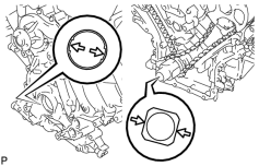
(f) Align the oil pump drive rotor spline and crankshaft as shown in the illustration. Install the spline and chain cover to the crankshaft. |
|
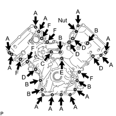
(g) Temporarily install the timing chain cover with the 28 bolts and nut. Standard Bolt:
NOTICE:
Make sure that there is no oil on the bolt threads. |
|
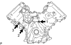
(h) Tighten the 3 bolts in several steps in the sequence shown in the illustration. Torque: 47 N·m (479 kgf·cm, 35 ft·lbf) |
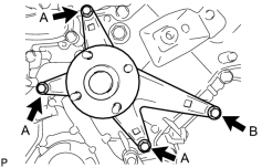
|
(i) Temporarily install the fluid coupling bracket with the 4 bolts. Standard Bolt:
|
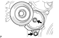
|
(j) Temporarily install the belt tensioner with the standard bolt and 6 mm hexagon wrench bolt. |
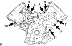
|
(k) Tighten the 8 bolts labeled 4 to 11 in several steps in the sequence shown in the illustration. Torque: 47 N·m (479 kgf·cm, 35 ft·lbf) |
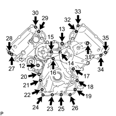
|
(l) Tighten the 23 bolts and nut labeled 12 to 35 in several steps in the sequence shown in the illustration. Torque: 23 N·m (235 kgf·cm, 17 ft·lbf) NOTICE:
After the installation, if the seal packing has seeped out at the areas labeled A shown in the illustration, wipe it off. |
3. INSTALL SPARK PLUG TUBE GASKET

4. INSTALL CYLINDER HEAD COVER SUB-ASSEMBLY LH
|
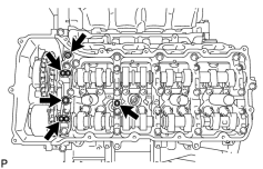
(a) Install 5 new gaskets to the camshaft bearing caps (No. 2, No. 3). |
(b) Install the gasket to the cylinder head cover.
NOTICE:
Remove any oil from the contact surface.
|
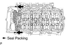
(c) Apply seal packing as shown in the illustration. Seal packing: Toyota Genuine Seal Packing Black, Three Bond 1207B or equivalent NOTICE:
|
|
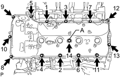
(d) Install the cylinder head cover and the seal washer with the 14 bolts in the order shown in the illustration. Torque: 21 N·m (214 kgf·cm, 15 ft·lbf) Torque: 12 N·m (122 kgf·cm, 9 ft·lbf) |
5. INSTALL CYLINDER HEAD COVER SUB-ASSEMBLY RH
|
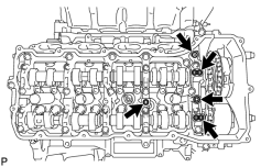
(a) Install 5 new gaskets to the camshaft bearing caps. (No. 1, No. 3). |
(b) Install the gasket to the cylinder head cover.
NOTICE:
Remove any oil from the contact surface.
|
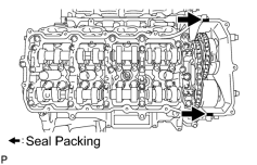
(c) Apply seal packing as shown in the illustration. Seal packing: Toyota Genuine Seal Packing Black, Three Bond 1207B or equivalent NOTICE:
|
|
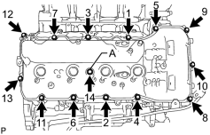
(d) Install the cylinder head cover and the seal washer with the 14 bolts in the order shown in the illustration. Torque: 21 N·m (214 kgf·cm, 15 ft·lbf) Torque: 12 N·m (122 kgf·cm, 9 ft·lbf) |
|
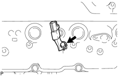
(e) Install the noise filter to the cylinder head cover with the bolt. Torque: 7.0 N·m (71 kgf·cm, 62 in·lbf) |
6. INSTALL IGNITION COIL ASSEMBLY
(a) Install the 8 ignition coils with the 8 bolts.
Torque: 10 N·m (102 kgf·cm, 7 ft·lbf)
7. INSTALL CRANKSHAFT TIMING GEAR KEY
|
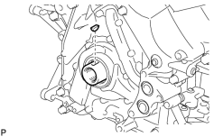
(a) Install the crankshaft timing gear key to the crankshaft. |
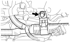
8. CONNECT WIRE HARNESS CLAMP BRACKET
|
(a) Connect the bracket to the timing chain cover with the bolt. Torque: 8.0 N·m (82 kgf·cm, 71 in·lbf) |
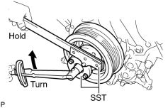
9. INSTALL CRANKSHAFT PULLEY
|
(a) Align the pulley set key with the key groove of the pulley, and slide on the pulley. |
(b) Using SST, install the pulley set bolt.
SST: 09213-70011
09213-70020
SST: 09330-00021
Torque: 300 N·m (3059 kgf·cm, 221 ft·lbf)
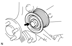
10. INSTALL NO. 1 IDLER PULLEY SUB-ASSEMBLY
|
(a) Install the idler pulley with the bolt. Torque: 43 N·m (438 kgf·cm, 32 ft·lbf) |
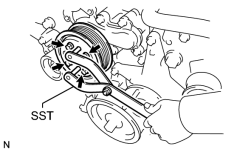
11. INSTALL WATER PUMP PULLEY
|
(a) Temporarily install the pulley with the 4 bolts. |
(b) Using SST, hold the pulley and tighten the 4 bolts.
SST: 09960-10010
09962-01000
09963-01000
Torque: 21 N·m (214 kgf·cm, 15 ft·lbf)
12. INSTALL WATER INLET HOUSING
|
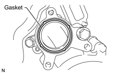
(a) Install a new gasket to the timing chain cover. |
|
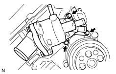
(b) Install the water inlet with the 3 bolts. Torque: 21 N·m (214 kgf·cm, 15 ft·lbf) |
13. INSTALL AIR TUBE SUB-ASSEMBLY
|
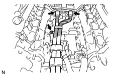
(a) Connect the 2 hoses. |
(b) Install the air tube with the bolt.
Torque: 10 N·m (102 kgf·cm, 7 ft·lbf)
14. INSTALL NO. 1 ENGINE COVER
15. INSTALL NO. 2 ENGINE COVER
16. INSTALL FRONT WATER BY-PASS JOINT
|
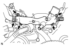
(a) Install 2 new gaskets and the water by-pass joint with the 4 nuts. Torque: 21 N·m (214 kgf·cm, 15 ft·lbf) |
(b) Connect the No. 2 water by-pass hose to the water by-pass joint.
17. INSTALL WATER BY-PASS PIPE SUB-ASSEMBLY
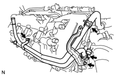
(a) Connect the 2 hoses.
|
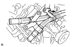
(b) Install the water by-pass pipe with the 2 bolts. Torque: 10 N·m (102 kgf·cm, 7 ft·lbf) |
|
(c) Connect the air tube with the bolt. Torque: 10 N·m (102 kgf·cm, 7 ft·lbf) |
18. INSTALL NO. 1 WATER BY-PASS HOSE
|
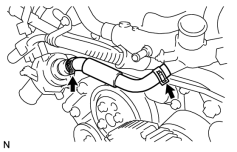
(a) Install the No. 1 water by-pass hose by connecting the hose to the water inlet housing and front water by-pass joint. |
19. INSTALL GENERATOR ASSEMBLY
20. CONNECT OIL COOLER PIPE ASSEMBLY
21. CONNECT VANE PUMP ASSEMBLY
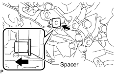
HINT:
Before performing the following procedures, move the spacer until the vane pump can be installed.
|
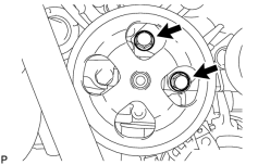
(a) Connect the vane pump to the timing chain cover with the 2 bolts. Torque: 21 N·m (214 kgf·cm, 15 ft·lbf) |
|
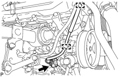
(b) Connect the 2 clamps and power steering oil pressure switch connector. |
22. INSTALL INTAKE MANIFOLD
23. INSTALL OIL FILTER BRACKET (w/o Oil Cooler)
|
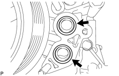
(a) Apply a light coat of engine oil to 2 new O-rings. |
(b) Install the 2 O-rings to the timing chain cover.
|
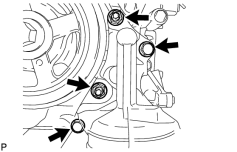
(c) Install the oil filter bracket with the 2 bolts and 2 nuts. Torque: 35 N·m (357 kgf·cm, 26 ft·lbf) |
24. INSTALL OIL FILTER BRACKET (w/ Oil Cooler)
25. INSTALL NO. 1 OIL COOLER BRACKET (w/ Oil Cooler)
26. INSTALL NO. 2 WATER BY-PASS PIPE SUB-ASSEMBLY (w/ Oil Cooler)
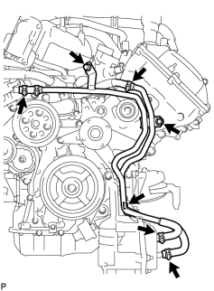
(a) Connect the 4 hoses.
|
(b) Install the water by-pass pipe with the 3 bolts. Torque: 10 N·m (102 kgf·cm, 7 ft·lbf) |
27. INSTALL OIL PRESSURE SENDER GAUGE ASSEMBLY
28. INSTALL ENGINE OIL LEVEL DIPSTICK GUIDE
29. INSTALL OIL FILTER ELEMENT
30. CONNECT NO. 2 FUEL TUBE SUB-ASSEMBLY
|
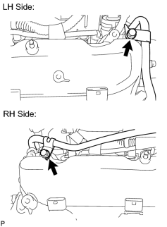
(a) Connect the fuel tube with the 2 bolts. Torque: 10 N·m (102 kgf·cm, 7 ft·lbf) |
31. CONNECT COOLER COMPRESSOR ASSEMBLY
|
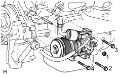
(a) Install the cooler compressor with the stud bolt. Torque: 10 N·m (102 kgf·cm, 7 ft·lbf) |
(b) Install the 3 bolts and nut.
Torque: 25 N·m (250 kgf·cm, 18 ft·lbf)
NOTICE:
Tighten the bolts and nut in the order shown in the illustration to install the cooler compressor.
32. CONNECT NO. 2 WATER BY-PASS PIPE
|
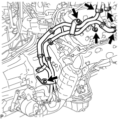
(a) Connect the No. 2 water by-pass pipe to the cylinder head cover with the 3 bolts. Torque: 18 N·m (184 kgf·cm, 13 ft·lbf) |
(b) Connect the 3 hoses.
33. CONNECT AIR PUMP HOSE AND WIRE HARNESS
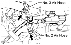
|
(a) Connect the No. 2 and No. 3 air hoses. |
(b) Connect the 2 clamps and air pump wire harness.
34. CONNECT ENGINE WIRE
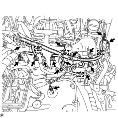
|
(a) Engine Room RH Side: (1) Connect the 5 clamps. (2) Connect the throttle position sensor and throttle control motor connector. (3) Connect the 2 air pump connectors. (4) Install the ground wire with the 2 bolts. Torque: 8.0 N·m (82 kgf·cm, 71 in·lbf) (5) Connect the noise filter connector. (6) Connect the 2 VVT sensor connectors. HINT:
The wire harnesses on the exhaust side are wrapped with white tape. (7) Connect the injector connector. (8) Connect the 4 ignition coil connectors. (9) Connect the 2 camshaft timing oil control valve connectors. HINT:
The wire harnesses on the exhaust side are wrapped with white tape. |
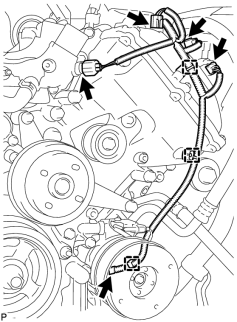
|
(b) Engine Room LH Side: (1) Connect the cooler compressor connector. (2) Connect the 3 clamps. (3) Connect the camshaft position sensor connector. (4) Connect the 2 camshaft timing oil control valve connectors. HINT:
The wire harnesses on the exhaust side are wrapped with white tape. (5) Connect the engine coolant temperature sensor connector. (6) Connect the 4 clamps. (7) Install the ground wire with the 2 bolts. Torque: 8.0 N·m (82 kgf·cm, 71 in·lbf) (8) Connect the noise filter connector. (9) Connect the 2 VVT sensor connectors. HINT:
The wire harnesses on the exhaust side are wrapped with white tape. (10) Connect the 4 ignition coil connectors. (11) Connect the injector connector. (12) Connect the wire harness clamp and 4 air injection control driver connectors. (13) Connect the 2 connectors and 2 clips to the engine room junction block. (14) Install the engine room relay block cover. |
35. INSTALL RADIATOR ASSEMBLY
(a) Install the radiator
.
36. INSTALL AIR CLEANER ASSEMBLY
37. INSTALL AIR CLEANER HOSE ASSEMBLY
38. INSTALL V-BANK COVER SUB-ASSEMBLY
39. ADD ENGINE OIL
40. ADD ENGINE COOLANT
41. CONNECT CABLE TO NEGATIVE BATTERY TERMINAL
NOTICE:
When disconnecting the cable, some systems need to be initialized after the cable is reconnected
.
42. INSPECT FOR OIL LEAK
43. INSPECT FOR COOLANT LEAK
44. INSPECT ENGINE OIL LEVEL
45. INSTALL NO. 2 ENGINE UNDER COVER
46. INSTALL NO. 1 ENGINE UNDER COVER SUB-ASSEMBLY
47. INSTALL FRONT FENDER SPLASH SHIELD SUB-ASSEMBLY LH
48. INSTALL FRONT FENDER SPLASH SHIELD SUB-ASSEMBLY RH
49. INSTALL FRONT FENDER APRON SEAL FRONT RH
50. INSTALL FRONT FENDER APRON SEAL LH
51. INSTALL COWL TOP VENTILATOR LOUVER SUB-ASSEMBLY
(a) Install the cowl top ventilator louver
.
52. CONNECT RADIATOR SIDE DEFLECTOR RH (w/o Air Cooled Transmission Oil Cooler)
53. CONNECT RADIATOR SIDE DEFLECTOR LH
54. INSTALL RADIATOR GRILLE
55. INSTALL UPPER RADIATOR SUPPORT SEAL
56. INSTALL ENGINE ROOM SIDE COVER RH
57. INSTALL ENGINE ROOM SIDE COVER LH

|

|