Timing Chain Cover Removal and Installation
Precautions: General safety (00)
Removal
1)Remove engine assembly from vehicle. 
2)Remove water pump / generator drive belt.
3)Remove crankshaft pulley bolt (1).
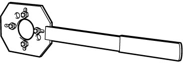
To lock crankshaft pulley (2), use special tool as shown in figure.
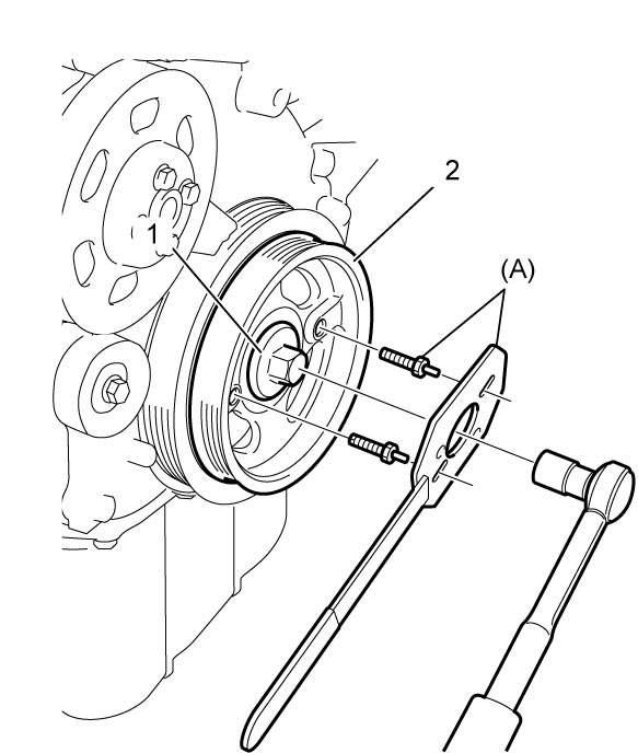

To lock crankshaft pulley (2), use special tool as shown in figure.
4)Remove crankshaft pulley (1).
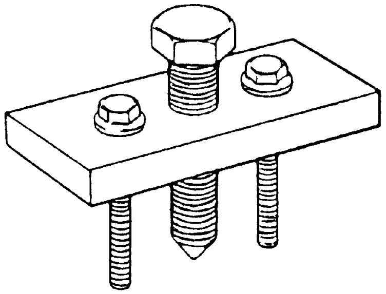
If it is hard to remove, use special tools.
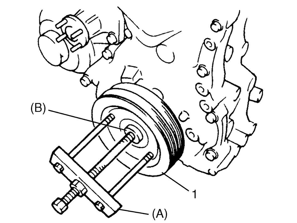
If it is hard to remove, use special tools.
5)Remove cylinder head cover.
6)Remove oil pan.
7)Remove water pump / generator drive belt tensioner pulley (1).
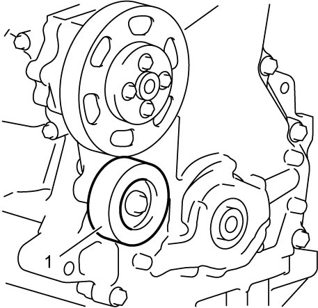
8)Remove water pump pulley.
9)Remove timing chain cover.
10)Remove crankshaft oil seal from timing chain cover using a flat-bladed screwdriver or the like, if necessary.
11)Remove timing chain cover O-ring (1), oil pump O-ring (2) and gasket (3).
12)Remove filter (4) from timing chain cover, if necessary.
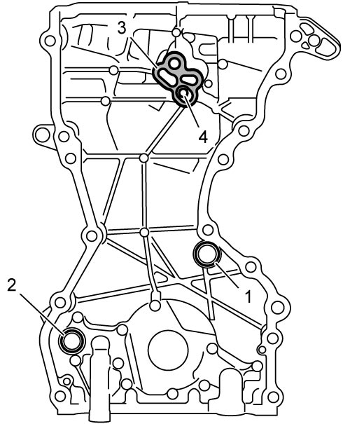
13)Remove OCV from timing chain cover, if necessary.
14)Remove oil pressure switch from timing chain cover, if necessary.
15)Remove oil pump from timing chain cover.
Installation
1)Clean mating surfaces of timing chain cover, cylinder block and cylinder head removing oil, old sealant and dust.
2)Install oil pump to timing chain cover, if removed.
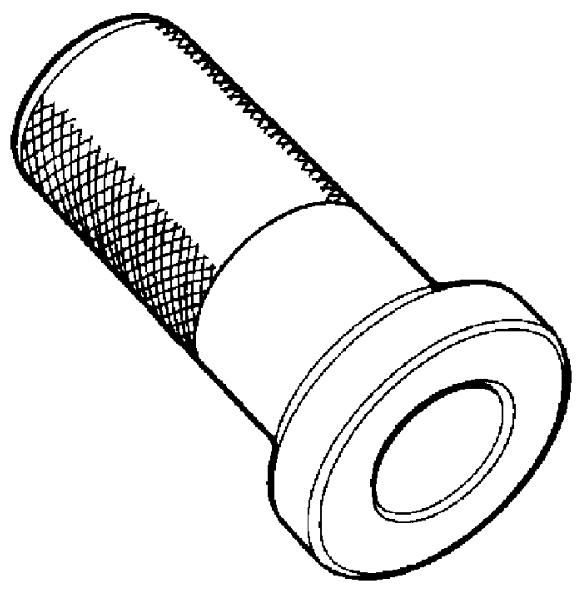
3)Press-fit new oil seal (1) into timing chain cover (2) using special tool (A) as shown in figure.
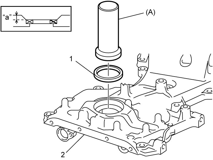
Depth
“a”: 2.25 mm (0.088 in.)
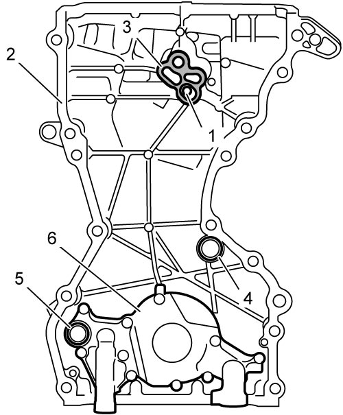
4)Check cleanliness of filter (1) and install it to timing chain cover (2), if removed.
5)Apply engine oil to new gasket (3) and install it to timing chain cover.
6)Apply engine oil to new timing chain cover O-ring (4), new oil pump O-ring (5) and install each one to oil pump (6) and timing chain cover.
7)Check that dowel pins are installed to cylinder block.
8)Clean mating surface of timing chain cover, cylinder block and cylinder head.
9)Clean mating portions (1) of cylinder block and cylinder head with cleaning solvent particularly.
10)Apply sealant “A” to mating surface of timing chain cover as shown in figure.
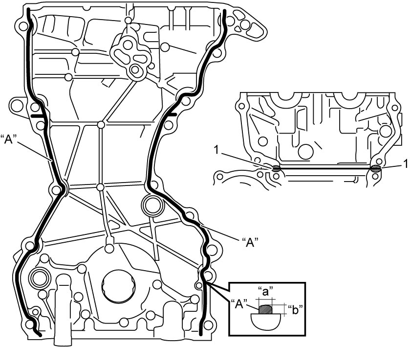
Sealant bead size for timing chain cover
Width “a”: 3 mm (0.12 in.)
Height “b”: 2 mm (0.08 in.)
11)Install timing chain cover noting the following points.
•Apply engine oil to oil seal lip.
•Align straight lines (1) of oil pump inner rotor with straight lines (2) of crankshaft sprocket.
•Install timing chain cover within 2 minutes after applying sealant.
•Check O-rings and gasket for proper fit.
•Use care so that oil seal lip is not damaged and oil seal spring is not coming off.
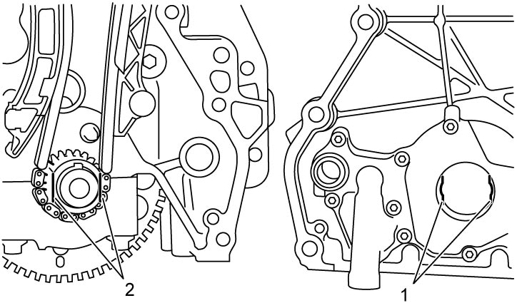
•Align straight lines (1) of oil pump inner rotor with straight lines (2) of crankshaft sprocket.
•Install timing chain cover within 2 minutes after applying sealant.
•Check O-rings and gasket for proper fit.
•Use care so that oil seal lip is not damaged and oil seal spring is not coming off.
12)Tighten timing chain cover bolts No.1 and No.2 in numerical order (“1” – “15”) evenly and gradually to specified torque.
Timing chain cover bolt No.2* (b): 25 N·m (2.5 kgf-m, 18.5 lbf-ft)
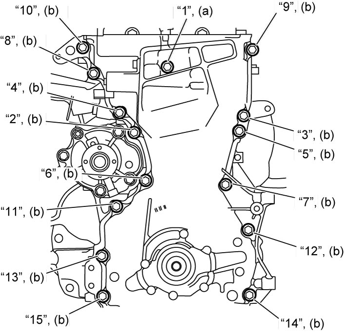
Tightening torque
Timing chain cover bolt No.1* (a): 25 N·m (2.5 kgf-m, 18.5 lbf-ft)Timing chain cover bolt No.2* (b): 25 N·m (2.5 kgf-m, 18.5 lbf-ft)
13)Wipe off excessive sealant squeezed out from timing chain cover at the lower end.
14)Install oil pressure switch to timing chain cover, if removed.
15)Install OCV, if removed.
16)Install water pump pulley.
17)Install water pump / generator drive belt tensioner pulley (1) and tighten water pump / generator drive belt tensioner pulley bolt (2) to specified torque.
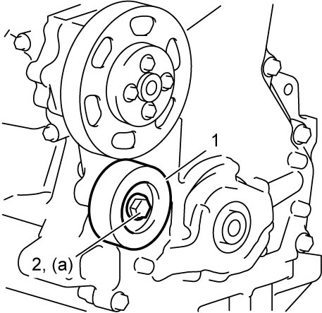
Tightening torque
Water pump / generator drive belt tensioner pulley bolt (a): 45 N·m (4.6 kgf-m, 33.5 lbf-ft)
18)Install cylinder head cover.
19)Install oil pan.
20)Install crankshaft pulley (1) and tighten crankshaft pulley bolt (2) to specified torque. To lock crankshaft pulley, use special tool as shown in figure.
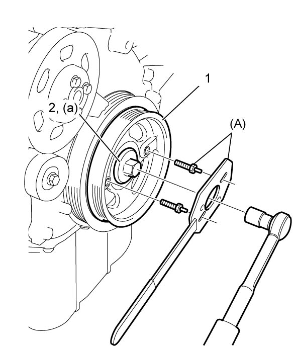
21)Install water pump / generator drive belt.
22)Install engine assembly to vehicle.